KU63 controller circuit board connections

LaurentDehaeck

Pedelecer
Jul 23, 2015
39
0
40
Hey , yes yesterday i read somthing about the brown , white an red cable .... Doesnt it have to do with the eu legislation ? This is what the dutch guy on the other website has to say .... I will definitly figure out what your telling me : as i am doing my sister a favor i have my hands dirty any way now :)

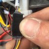
Where do i find sensor ? Is this what you mean ?? Ill send pics after this


Pedelec legalisation device
Contents[Hide]
1. Introduction
Many Chinese motor controllers can be used without pedalling, which is not allowed for pedelecs. Here we need additional electronics that adds the extra functionality to meet the EPAC standard. I developed a pedelec legalisation device which can be built into the motor controller. In German this is called a Gasgriff Freischalter. It is built with a 1MHz Atmel ATtiny85. The motor runs only when we pedal forward and the speed is below 25kmh. Start up assistance to 6 km/h without pedalling is omitted.


ATtiny 45/85 available pins


Pedelec legalisation device


2. Software safety precautions
I use a two position speed switch instead of a throttle. This requires special safety precautions against inadvertent switching on the motor, which can be perilous. This is because a throttle, in contrast to a switch, automatically springs back into the off position. A throttle is controlled consciously, a switch can stay in a certain position unnoticed. See also the disclaimer.

3. Properties
The motor is disabled when:

  • Not pedalling forward
  • Speed above 27.5km/h
  • Speed below 3km/h
4. PAS sensor SS461A
A digital Hall-effect device SS461A is used as PAS sensor and glued with epoxy directly to the bicycle frame. An advantage of the SS461A is the built in reverse voltage protection. Five magnets are glued into the chainring.


PAS sensor SS411P


5. Speed sensor
The bicycle speed is measured with a speed sensor from a cheap cycle computer (€3); it contains a reed relay and a spoke magnet.

6. Pedelec legalisation device circuit
Here is an example of how the pedelec legalisation device is connected to a motor controller. Download the circuit high definition pdf file here.


Pedelec legalisation device circuit


7. Pedelec legalisation device software
This software is not public.


Do you have any comments? Please let me know.

This work is licensed under a Creative Commons Attribution-NonCommercial-ShareAlike 3.0 Unported License.
image.jpg image.jpg image.jpg image.jpg image.jpg image.jpg image.jpg
 
D

Deleted member 4366

Guest
You need to follow the brown wire to see where it goes.
 

LaurentDehaeck

Pedelecer
Jul 23, 2015
39
0
40
There's still another trick. If the wheel size doesn't work, the controller must be getting the speed directly from the motor.

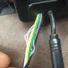
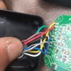
The speed signal comes down the white wire from the motor as one 5v pulse each revolution. I see your white wire joins a brown one, which then goes out of the controller. Where does it go?

The idea is to get a pulse at a lower frequency from another sensor. You can take a sensor from a cycle computer. It will have two wires. You cut the white wire from the brown one on your bike and connect one wire from the new sensor to the brown one and the other to any 5v position on the controller where the throttle and PAS get their 5v from. You then glue a magnet to the inside of your crank arm and fix the sensor to a chainstay so that it will pulse with your cadence instead of the wheel rotation.
 

Attachments

D

Deleted member 4366

Guest
I say again, you need to follow the brown wire to see where it goes.
 
D

Deleted member 4366

Guest
The microprocessor in the display is reading the motor speed directly, so the only thing you can do is is the tick I mentioned earlier with a cycle computer sensor or a reed swith. You can buy cycle computers from Ebay for maybe three Euros if you don't have an old one lying around.
 

LaurentDehaeck

Pedelecer
Jul 23, 2015
39
0
40
The microprocessor in the display is reading the motor speed directly, so the only thing you can do is is the tick I mentioned earlier with a cycle computer sensor or a reed swith. You can buy cycle computers from Ebay for maybe three Euros if you don't have an old one lying around.
Well inwill defintly follow your advice , as it is the least incan do for all your effort ! Thank youuuuu sooooo much ... I will try to do this on my own :) if you ever come to belgium ! You are my guest and if you live in the US OR UK ... LET ME KNOW YOUR ADRESS ...... I WILL BE HAPPY TO SEND YOU A PACKAGE FROM OUR FACTORY
 

LaurentDehaeck

Pedelecer
Jul 23, 2015
39
0
40
Well inwill defintly follow your advice , as it is the least incan do for all your effort ! Thank youuuuu sooooo much ... I will try to do this on my own :) if you ever come to belgium ! You are my guest and if you live in the US OR UK ... LET ME KNOW YOUR ADRESS ...... I WILL BE HAPPY TO SEND YOU A PACKAGE FROM OUR FACTORY
Should i try all the settings again in case i really missed somthing or is it a waste of time ?
 
D

Deleted member 4366

Guest
It would be a good idea to give it one more try, just in case you missed something.
 

LaurentDehaeck

Pedelecer
Jul 23, 2015
39
0
40
It would be a good idea to give it one more try, just in case you missed something.
Ok i got everything i need i guess ... Will have some questions soon ... Ill show you on a video if it is correct what i will do based on what you told me !
 
D

Deleted member 4366

Guest
Cut the white wire off the brown one and insulate the end of it. Join your sensor wire to the brown one. You can connect the other sensor wire either directly to the 5v pads on the pcb, or you can splice it to the red throttle or PAS wire. It makes no difference. You should then test that it works. Run a magnet past the sensor a few times quickly to see if you get a speed on the display. If not, you might have to join the sensor wire to ground instead of the 5v. The one I did was on the 5v, but it can be possible to be the other way round. For testing, it might be a good idea to solder direct to the PCB 5v because if it's wrong, it's easy to unsolder it and resolder to the 0v.
 

LaurentDehaeck

Pedelecer
Jul 23, 2015
39
0
40
Cut the white wire off the brown one and insulate the end of it. Join your sensor wire to the brown one. You can connect the other sensor wire either directly to the 5v pads on the pcb, or you can splice it to the red throttle or PAS wire. It makes no difference. You should then test that it works. Run a magnet past the sensor a few times quickly to see if you get a speed on the display. If not, you might have to join the sensor wire to ground instead of the 5v. The one I did was on the 5v, but it can be possible to be the other way round. For testing, it might be a good idea to solder direct to the PCB 5v because if it's wrong, it's easy to unsolder it and resolder to the 0v.
It didnt work on the 5v and i changed it to ground an when i pass the magnet it indeed reeds speed on the display but my wheel doesnt move ..... Now how does this influence the speed ?
 
D

Deleted member 4366

Guest
You glue a magnet to the back of your crank and fix the sensor to the chainstay. This will tell the controller the crank speed instead of the wheel speed. Everything will work the same. When you pedal, the pedal sensor will cause the controller give power., but the speed will read too slow, so it won't limit the speed anymore because it thinks you're going slower than you actually are. Without any speed signal, the controller eill default to 25 km/h, and also it will go to sleep after a few minutes, which is why you need to get some pulsing from somewhere.
 

LaurentDehaeck

Pedelecer
Jul 23, 2015
39
0
40
You glue a magnet to the back of your crank and fix the sensor to the chainstay. This will tell the controller the crank speed instead of the wheel speed. Everything will work the same. When you pedal, the pedal sensor will cause the controller give power., but the speed will read too slow, so it won't limit the speed anymore because it thinks you're going slower than you actually are. Without any speed signal, the controller eill default to 25 km/h, and also it will go to sleep after a few minutes, which is why you need to get some pulsing from somewhere.
In my opnion nothing changed