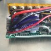
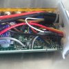
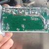
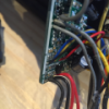
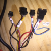
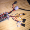
KU63 controller circuit board connections

eHomer

Esteemed Pedelecer
Aug 20, 2012
635
164
Thanks for bearing with me on this, and the very prompt replies.

So it definitely looks as though my PAS level switching wire from the 790 panel is wrongly connected to ZF, hence jamming it in PAS level 3.

Looking again at the reverse side of my panel, I don't see any unmarked pads near ZL though.

I've searched the web for a circuit diagram of the KU65, but can only find the KU63. new connections.jpg
 
D

Deleted member 4366

Guest
I'll have to look inside one again. My table seems to be missing a connection for the KU65. I.m pretty sure that PAS sensor signal is ZL, but need to check the PAS level green wire from the controller. I'll do it tonight if you can wait. Ithink you diagram is correct though.

The ZF that I referred to in post 18 is not actually ZF, but a pad near to it.
 

eHomer

Esteemed Pedelecer
Aug 20, 2012
635
164
Thanks Dave, once again thanks for taking so much trouble over helping.

If only I had taken a photo of the damn thing before I cut away that non-standard loom when I changed it out for the SO6S.

I didn't realise there would be such a dearth of circuit diagrams for the KU65.

I'm taking it apart this afternoon and will have a good look at the solder points to see which ones may have had a connection before, and check for short circuits.

If I have any success I'll get straight back on here, to save you opening yours up.
 

eHomer

Esteemed Pedelecer
Aug 20, 2012
635
164
Please don't bother to open up your controller for me Dave.

I've had a tinker with it, unsoldered the green wire back from the panel, but the motor still spins at what looks like max whenever the pedals are turned.

It's my fault, I think I've messed it around too much with cutting the leads and then resoldering, the board workmanship wasn't that good to start with.

I've had a better idea now. I think I'll get a new sinewave controller from BMS for my "best" bike, the Giant Trance with the MXUS cassette motor that I got from you. I'll shift that existing controller on to this bike. It's much more deluxe than the KU65, with 5 level PAS and throttle start.

I was thinking of the S12S 500w for the MXUS on the Trance, and knobbling the shunt down to about 350w. to not overload the motor and also give the controller an unstressed life.

Also,as I understand it, the S12S is available in switchable 36/48v, whereas the SO6S is only available in switchable 24/36v.

So with the downgraded S12S I'll have the option to use a 48v battery, when I eventually get one.
 

eHomer

Esteemed Pedelecer
Aug 20, 2012
635
164
Sounds like a good plan.
I've now transfered the other controller over, and it's much better than the KU65.

A wide range of very clearly stepped levels of assist, and throttle start.

My "spares box" Dahon has turned out to be a very nice conversion. In fact, if I ever had to downsize to one bike (perish the thought), it would be a real contender.

15 to 18mph performance, yet still very light and foldable.
 

petr

Finding my (electric) wheels
Jul 12, 2015
8
1
75
Praha, Czechia
www.lampa.cz
Hallo d8veh,

I found this thread very interesting, I highly appreciate your care and patience. Please could you add the PAS level input pin (ZF or other? = the green wire from the LCD controller) to your table of KU65 pins published here on Mar 25, 2014?
Due to European restrictions I have recently added a PAS input to my KU63 (it has been working on throttle only for long), and now I need some finer control of it. As the KU63 and KU65 are basically the same (may be different firmware but I don't believe), I would like to simulate the LCD controller signal and feed the KU63 on the correct pin which I don't know as exactly only this info is missing everywhere. Thanks.
 

LaurentDehaeck

Pedelecer
Jul 23, 2015
39
0
40
IMG_0472.JPG IMG_0474.JPG IMG_0475.JPG IMG_0477.JPG IMG_0479.JPG IMG_0482.JPG Hello to all,

4 months ago i invested in a Folding e-bike(1800 euros : Swyff - minimax 8 ) as i got my driver license suspended ..... although i had no other option then to take the bike ..... since i bought my new bike i am a happier man !!!!! I think i might have fallen in love with my bike. Although i was told it was a complete belgium production ....after doing my research on how i can speed up my bike ... i realized thanks to all you that my controller is exactly like yours but as well in mine there are different cables in different position en de PAS look more advanced ... meaning tiny and small compaired to yours ....

Now i am no expert in circuit bords at all , so that is why i am asking for your help ....

Before finding this forum and http://www.avdweb.nl/ , i followed the suggestions to bypass the power or somthing .... you will see on the pictures i took what i mean .... and it actually gave me a bit stronger torque and drives 27 km where before only 25.....km

now i dont want my bike to drive crazy speeds but i just want it to do fully what it is capable of with my current controller ..... it is ofcourse with a display and 6 assist speeds as well 8 manual gear

Kader
Aluminium vouwbaar en lage instap
Batterij
396Wh of 540Wh Lithium Mangaan
Motor
250W motor in naaf voorwiel verwerkt
Oplaadtijd
4-6 uur
Actieradius
55-120 km per laadbeurt*
Display
Digitaal 6 standen, met vertrekhulp
Versnellingen
Shimano Nexus 8 naafversnellingen
Remmen
V-brake voor en geventileerde rollerbrake achteraan
- See more at: http://www.swyff.com/nl/swyff-minimax-8-140.htm#sthash.CqSDXFfM.dpuf
 

Attachments

Last edited:
D

Deleted member 4366

Guest
The speed can be restricted by the controller or the motor. If it's limited by the motor, you will get a lower speed when he battery is empty than when full. If the peed is always the same, it's limited by the controller. The controllers are very cheap. You can buy some from BMSBattery to experiment with. Theirs are not restricted.

On yours, make sure pas XS is not grounded internally or extenally by two white wires.
 

LaurentDehaeck

Pedelecer
Jul 23, 2015
39
0
40
Thank You very much for your answer and i know for a fact that speed is limited by controller, as the speed alwys stays 25 even when the battery is low . And the PAS xs is neither grounded internally nor externely by two white whires.

So am i right to conclude, that by eliminating the pas i can reach the full speed it is capable to do whitouth hqving to change neither the motor or the controller ?
And if this is correct what i am assuming can you tell me how te eliminate the pass ? do i cut the 3 different color wires and thats it or do i need to adjust something else ?

kind regards
 
D

Deleted member 4366

Guest
The pedal sensor can't limit speed. XS is independent of PAS. It's a simple digital input to the CPU (on/off switch). It's held up at 5v for normal operation, and when grounded, the CPU restricts the speed. That's assuming that the CPU's software is programmed that way. It could be programmed to use any of the many other digital inputs for speed limit, but that's not very probable. One thing I notice about yours, which is different to the others is that SH is shorted to SL. My one couldn't work like that because SL needs to be 5v and SH needs to be 0v for it to give power, so yours could well be programmed differently. Where does your brake signal wire go? Where do those two grey wires go?

If you don't want to use PAS, unplug it. If you want to temporarily disable it while riding, put a switch on the signal wire.
 
Last edited by a moderator:

petr

Finding my (electric) wheels
Jul 12, 2015
8
1
75
Praha, Czechia
www.lampa.cz
The pedal sensor can't limit speed. XS is independent of PAS. It's a simple digital input to the CPU (on/off switch). It's held up at 5v for normal operation, and when grounded, the CPU restricts the speed.
On older versions of KU63, the white wire "speed limit" pulled down the XS pin across the resistor R87 to the Throttle CPU input. They probably changed it - after 2014, they simply pull down E4. The pin XS still remains on the board unconnected, it can be used for user speed limitation changing the R87 (20k) to some user value, and soldering another "white wire" on XS. (The change of R81 suggested by van Dalen gives me no sense as the internal resistance of the throttle sensor is about 100 ohm only.)
 
D

Deleted member 4366

Guest
I think there's a few mistakes in his schematic, especially in the areas where he's done modifications.
 
D

Deleted member 4366

Guest
I don't have access to that spreadshhet now. It's on a computer I don't use anymore.
 

LaurentDehaeck

Pedelecer
Jul 23, 2015
39
0
40
09ac7464-80e4-4905-b71c-945d0a0b872f.png
The pedal sensor can't limit speed. XS is independent of PAS. It's a simple digital input to the CPU (on/off switch). It's held up at 5v for normal operation, and when grounded, the CPU restricts the speed. That's assuming that the CPU's software is programmed that way. It could be programmed to use any of the many other digital inputs for speed limit, but that's not very probable. One thing I notice about yours, which is different to the others is that SH is shorted to SL. My one couldn't work like that because SL needs to be 5v and SH needs to be 0v for it to give power, so yours could well be programmed differently. Where does your brake signal wire go? Where do those two grey wires go?

If you don't want to use PAS, unplug it. If you want to temporarily disable it while riding, put a switch on the signal wire.
So the two grey wires : - ONE GOES TO DISPLAY /AND ONE TO BRAKE
ON +5 V: THEIR ARE 2 red wires that each go brake and axis sensor
on GND ; TWO BLACK WIRES GO EACHT TO BRAKE AND AXIS SENSOR
AND IN BETWEEN THOSE 4 WIRES THEIR IS A WHITE WIRE GOING TO DISPLAY A
 
Last edited:

LaurentDehaeck

Pedelecer
Jul 23, 2015
39
0
40
86701a88-9a7b-480e-8166-7f57a3dbd89b.png b9cdbbc0-4d4a-44bd-96d4-0a4418b298fb - kopie.png
I don't have access to that spreadshhet now. It's on a computer I don't use anymore.
So the two grey wires : - ONE GOES TO DISPLAY /AND ONE TO BRAKE
ON +5 V: THEIR ARE 2 red wires that each go brake and axis sensor
on GND ; TWO BLACK WIRES GO EACHT TO BRAKE AND AXIS SENSOR
AND IN BETWEEN THOSE 4 WIRES THEIR IS A WHITE WIRE GOING TO DISPLAY A
 
Last edited:

petr

Finding my (electric) wheels
Jul 12, 2015
8
1
75
Praha, Czechia
www.lampa.cz
I don't have access to that spreadsheet now. It's on a computer I don't use anymore.
Although the updated table of KU63/65 pins would be practical generally, of course you do not have to do it now. I just need only one missing item to be able to simulate the LCD controller signal and feed the KU63. This is a simple info as e.g. "the green wire 1...4V feeds the ZF (?)" or any other pin on the KU65.

Please excuse very much me for bothering you, I tried to find it everywhere but was not lucky. Thank you.