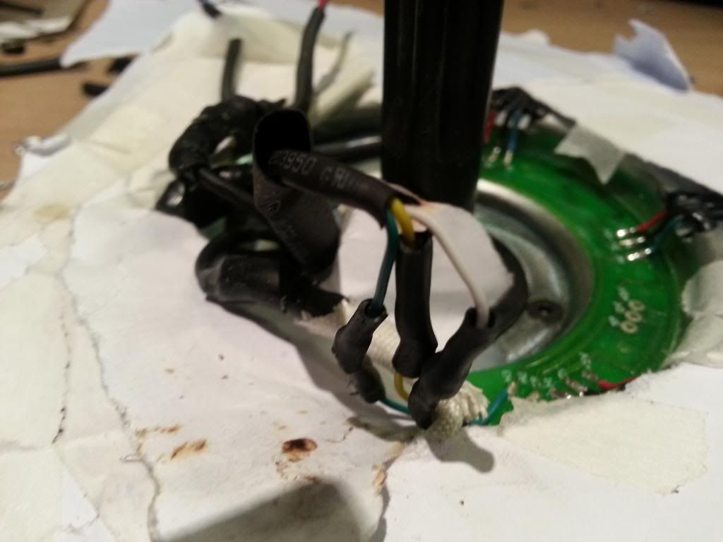
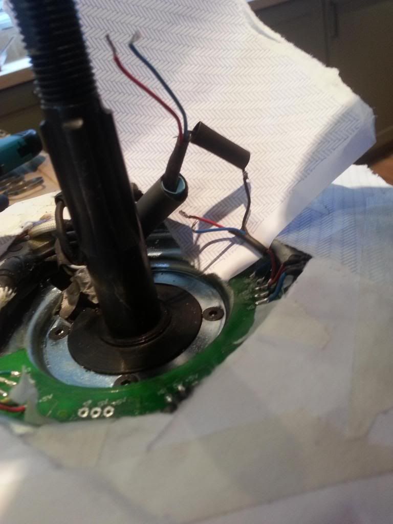
Broke my motor lead - new motor (and wheel build) or is it replaceable ?

D

Deleted member 4366

Guest
You're getting a bit mixed up. I don't think anybody said tap the nut, but here it is again:
Place the motor on blocks or whatever so that it's supported on the side-plate and hanging in the air.
Tap the axle on the spline side and the motor will go towards the floor. It'll probably go a bit at a time, then suddenly drop, so be ready to catch it.
If the axle end goes down to the end of the spline and the motor still hasn't dropped, then you need a drift (bar or large bolt or something) to knock it through the spline.

If you want/need to remove the clutch:
Undo the nut on the axle opposite side to spline
Slide off clutch with gears. Look out for a key on the shaft. Don't lose it. Some shafts havve a spline rather than a key.
 

morphix

Esteemed Pedelecer
Oct 24, 2010
2,163
119
Worcestershire
www.cyclecharge.org.uk
Possible spring alternative

It just occurred to me you might be able to use something like this to reinforce your cable Alex:


Assuming you can find the right size..?
 
Last edited:

103Alex1

Esteemed Pedelecer
Sep 29, 2012
2,228
67
Yep - got a spare one of those from the old kettle plugs. I'll fiddle around with it when I've got in to the motor and worked out the fix.

Got the plate off

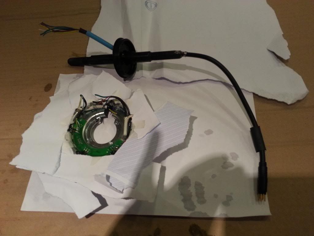
Okay... got it off :


103Alex1

Esteemed Pedelecer
Sep 29, 2012
2,228
67
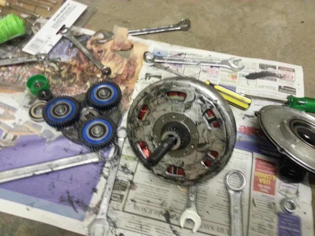
Another step completed with d8veh's help on live Skype ... gears removed. Clutch plate was wedged on tight down a central spline on the axle on this motor. Couldn't shift 'em by hand at all. Thought a 3-pronged clutch remover might need to be found but improvised (carefully) with the ratchet end of 3 spanners from a Lidl set popped in between the casing and the clutch plate between the outer gears. Used my knee on one and one hand on each of the others applying as even lever pressure on all 3 as I could and it began to shift. Taking real care not to damage the gears as it levered up.

Another round with a bigger set of spanners needed to get it all the way off :


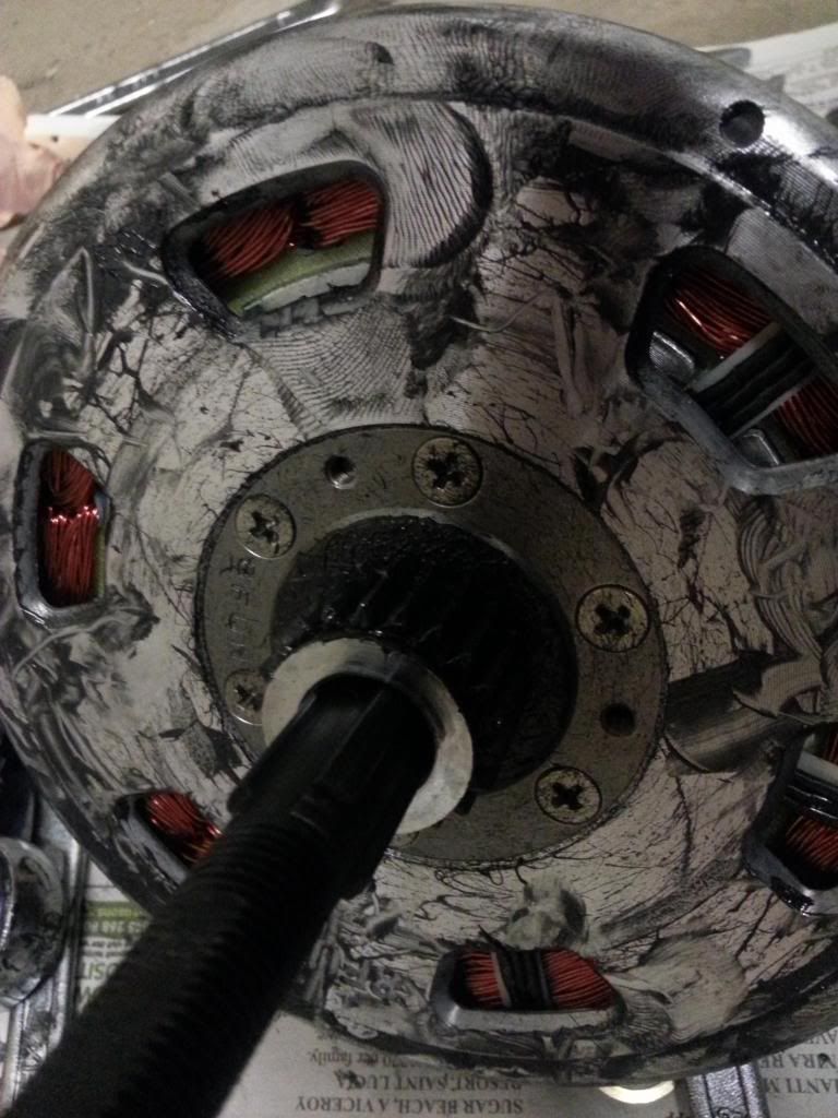
You can now see the spline the clutch slots into on the axle in the 2nd photo.

I guess now the next job is to get those screws shifted ? They're blooming tight - didn't budge at all with my Halfords short handed screwdriver :eek:. Will try to find a longer one to get a bit more purchase on them.
 

shemozzle999

Esteemed Pedelecer
Sep 28, 2009
2,826
686
Yep - got a spare one of those from the old kettle plugs. I'll fiddle around with it when I've got in to the motor and worked out the fix.

Got the plate off

Okay... got it off :


When I zoom in on the photograph it looks like one of the magnets at the top to the left is displaced.

They are glued in place during manufacture and will have to be re-glued if loose before re-assembly.

Also, now that the coils are exposed you have to be very careful not to damage them in any way or the motor will be totally fubar.

Kudos for getting this far but I would seriously consider letting someone else finish off the job.
 
Last edited:

103Alex1

Esteemed Pedelecer
Sep 29, 2012
2,228
67
I have the core out and no damage to the magnets either on the outer ring (where the displaced one was) or on the inner core - the one that looks displaced just slid back into position with a plastic tyre lever on the outer plate. The inner magnets are glued in to the core but the ones on the outer plate are just held in place by magnetic force.

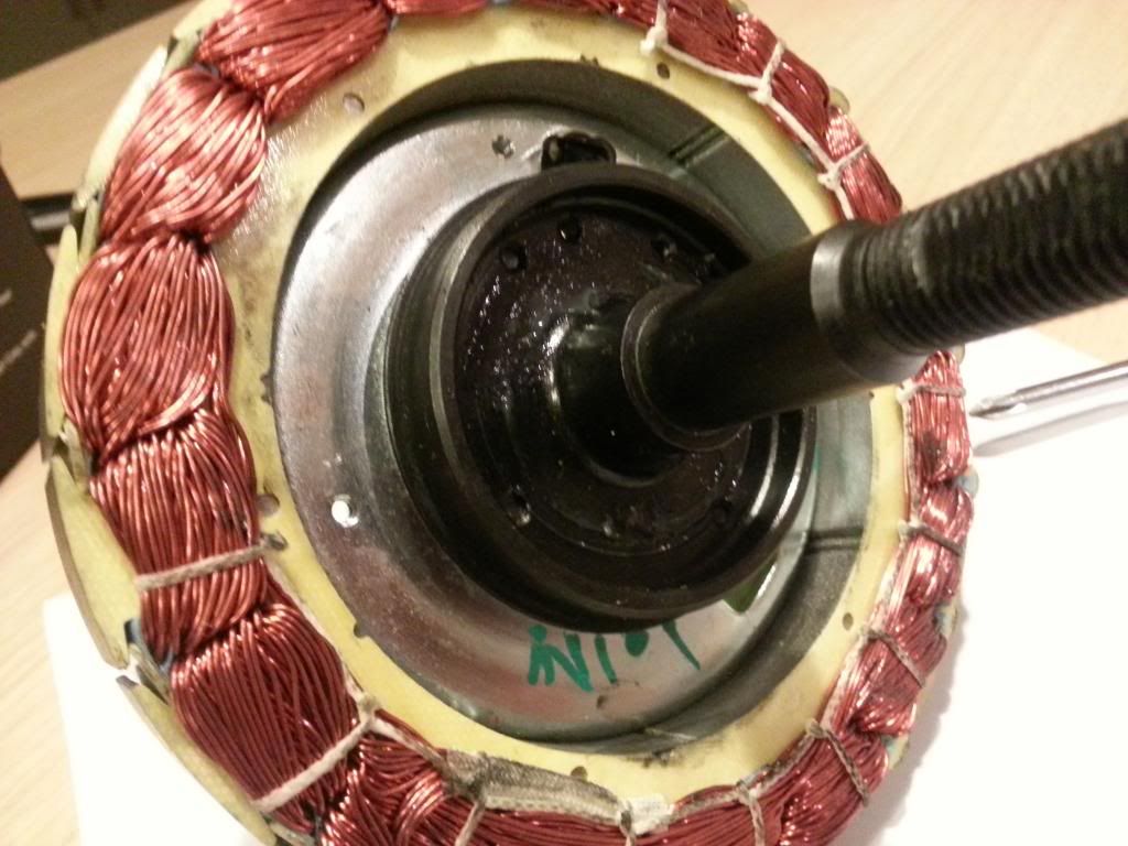
Turns out the central gear doesn't have to be removed at all. the outer case just slid straight off when I pushed down on it against the magnet force with the relevant axle end vertical on the floor.

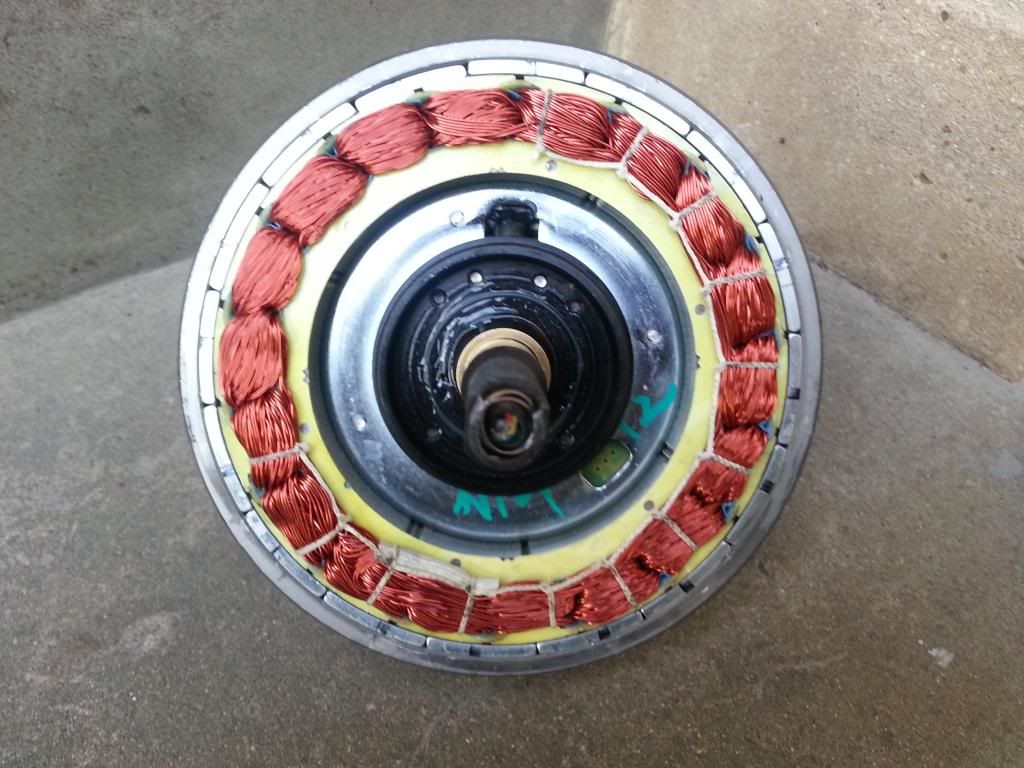
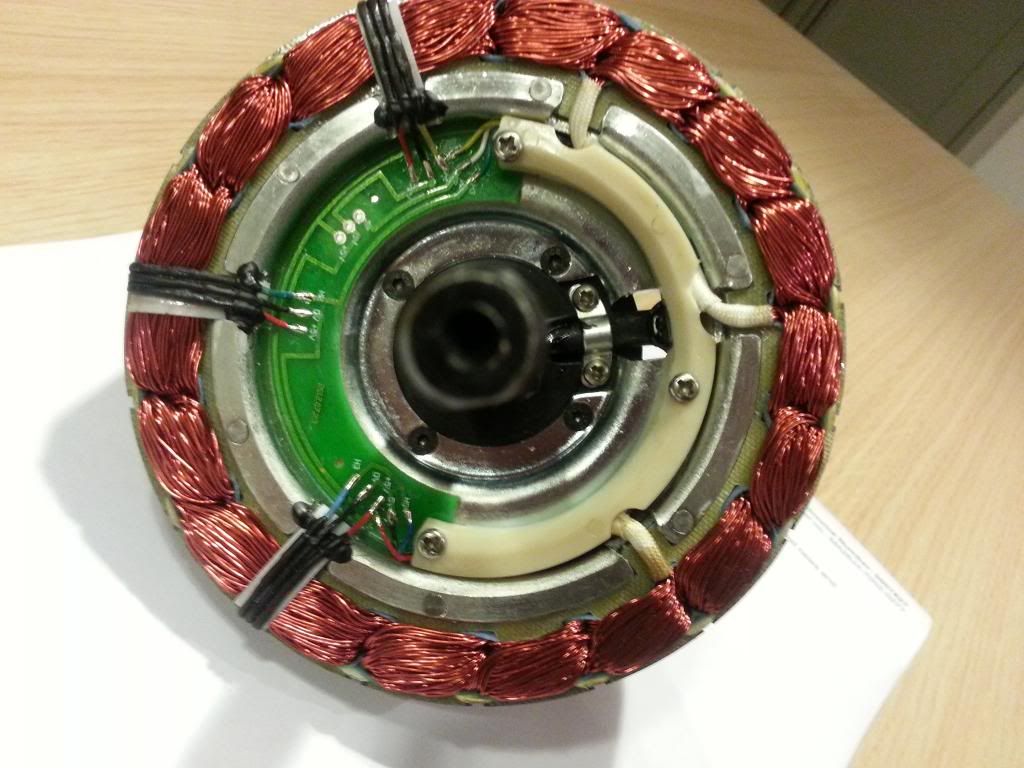
This is what's inside :


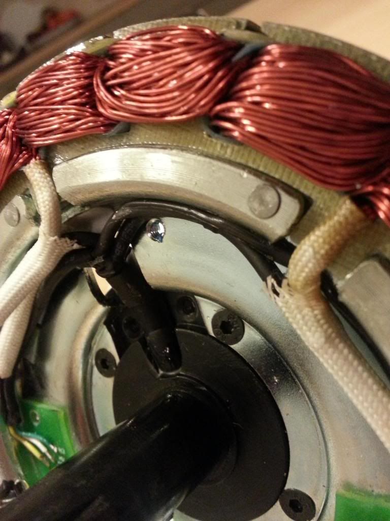
... and after the little white plastic cover over the branch cabling from the central wire coming in is unscrewed and the bracket over the main cable in wire unscrewed :


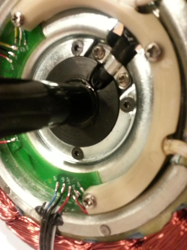
My guess is that any repairs are only needed at the points the wires branch away to the right and left (looks like the Hall sensor wires are separate cables that likely are solder-joined to the main cable around there somewhere.

There's a lot of some form of sealing compound used at that join along about 1cm of shrinkwrap where the feeder cables branch off to the PCB. The only way to know for sure is when the surgery is performed I guess.

I have a tube of Servisol silicone adhesive sealant I my guess is that the cabling is glued down in place with something like that between the axle exit point inside the motor and the plate behind.

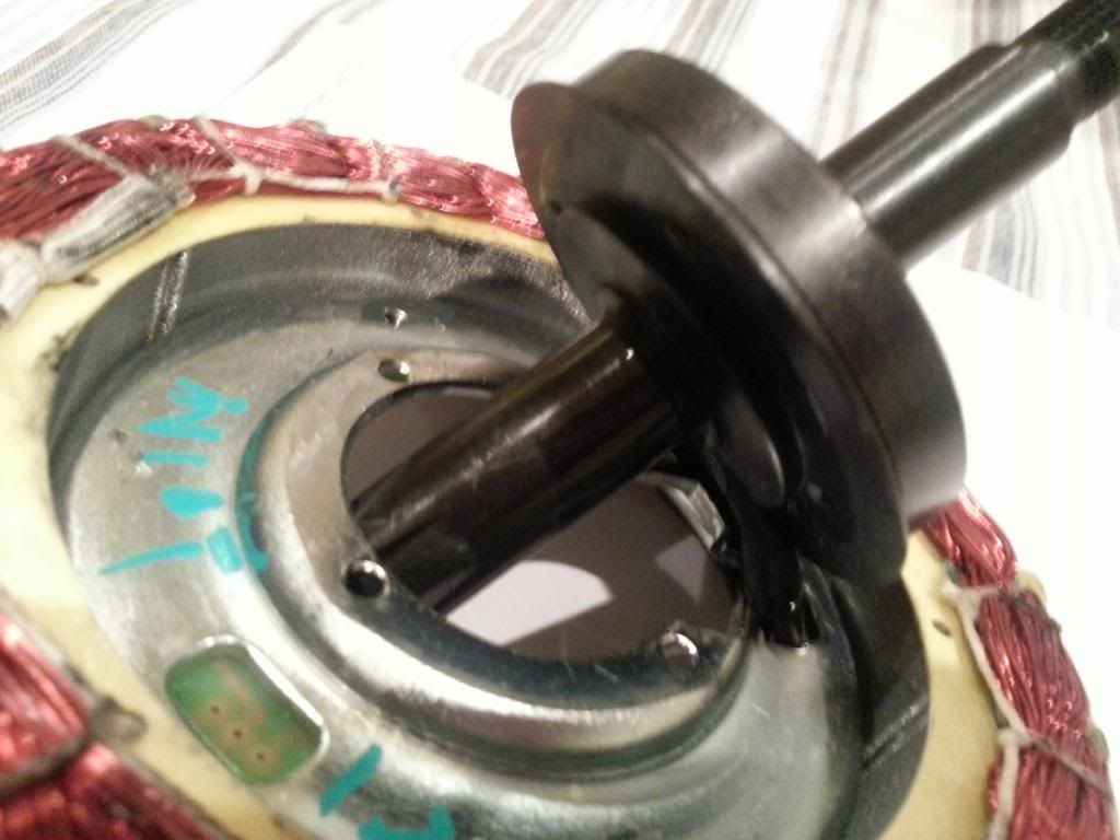
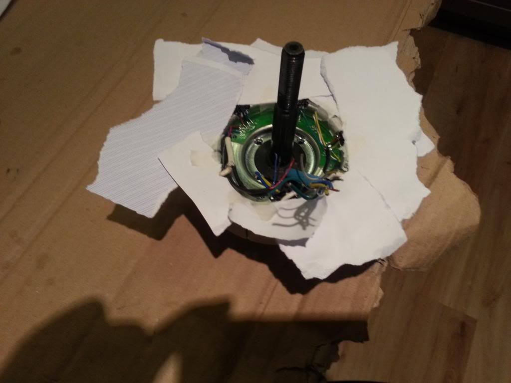
There still seems to be one removeable piece now this end is open - the 4 black hex screws on the PCB side attach the central black plate on the opposite side to the core. When this comes off I suspect we'll see the cable exit from the axle. Seen here (still attached) :


Also, now that the coils are exposed you have to be very careful not to damage them in any way or the motor will be totally fubar.
Thanks for the warning. The coils are fine - no damage. Don't worry I'm extremely careful. My choice of career was going to be a surgeon for most of my formative years lol... until the reality of all that cutting and mess sunk in after watching an eye surgeon do a conveyor belt of operations in a makeshift bush hospital at a tender age. Never regretted changing my mind !!
 
Last edited:

103Alex1

Esteemed Pedelecer
Sep 29, 2012
2,228
67
Axle unscrewed - but doesn't tell us much more than we can already see to be honest :


I've screwed it back in place for now. So the $350 question is .... how to get the old cable out and the new cable in and where / how it fixes in (i.e. solder incoming cable to the Hall / 3-phase feed wires at the central point where the cable exits the axle or some other setup where they are fanned out and connected at different points round the motor) ...

and also to find out what's hiding under those cloth cable covers that are feeding to the copper wiring (the 3-phase wires if I were to hazard a guess ! ) ...

I'm going to stop now to reflect and have a break. Good to have got to a point where the real job can begin !!
 
Last edited:

103Alex1

Esteemed Pedelecer
Sep 29, 2012
2,228
67
Long chat with d8veh earlier - we've basically agreed best thing to do is splice the new phase wires on to the old to avoid dismantling the connections to the the copper wounds. I'm going to do my best to solder together somewhere the new join can be glued to the edge with silicone adhesive when everything's complete.

The Hall sensor wires will also be spliced if I can (they are very thin and fiddly). If not they'll need to be soldered to the PCB in place of the original ones. I'm a bit worried about doing that to be honest as it's such a precise job and needs a very fine soldering tip. I've got the soldering aids now for this sort of thing - but even so !!

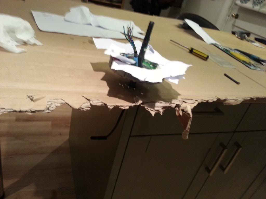
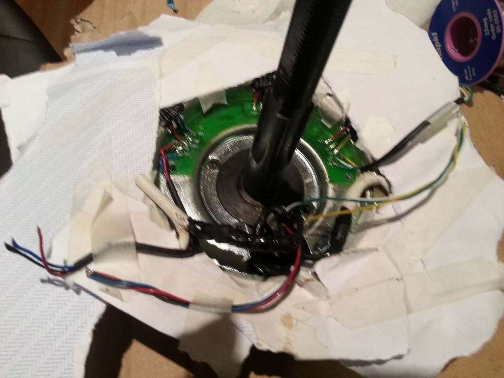
Patient prepped for major surgery ... in my makeshift cardboard "clamp" array. I worked out how to do this on my first soldering job fitting 12AWG wires to Deans connectors (about 3 weeks ago now I think !) ... and it's very effective if you've not got all the best tools in the cupboard :) :


johnc461165

Esteemed Pedelecer
Aug 19, 2011
546
22
WN6
Alex you have done really well, keep going, this is one of the best posts ever. I wish you all the best in your repair and must add that Dave is a hero for helping you.
 

103Alex1

Esteemed Pedelecer
Sep 29, 2012
2,228
67
Still going well. I've sorted the 3 phase wires and completed 3 of the 6 mini sensor wires. It's quite a job but taking my time over this now after the initial fiasco from impatient short-cuts !! It's all making short work of my stocks of solder and heatshrink ... glad I had some of it in. Got some more pics of the repair but no time to post at the moment. I'll get some up this afternoon or evening hopefully once I've finished the rest of the wiring.

Need some kip - got people coming round later this morning :eek: :rolleyes:

Alex you have done really well, keep going, this is one of the best posts ever. I wish you all the best in your repair and must add that Dave is a hero for helping you.
Cheers - the encouragement is much appreciated - must confess I was pretty daunted initially when that motor started coming apart ... but d8veh has helped me through every stage by Skype and we're learning new things about the motor along the way ... discovered there is circuitry for a temperature sensor on the PCB which the white sensor wire traces to on the PCB so weighing up whether to put one in when the repair work's done before the motor is closed up. It's all good stuff to know & it's only by doing stuff like this you find these things out :cool:

Dave is being amazing - it's actually a privilege to get to learn from him on something like this !
 

shemozzle999

Esteemed Pedelecer
Sep 28, 2009
2,826
686
The extra wire in the 9pin connector is for connecting to a factory fitted additional speed sensor option.

The loose magnet needs to be glued in place (superglue the top and bottom edges) or it could be pulled onto the stator when the motor is energized.
 
Last edited:

morphix

Esteemed Pedelecer
Oct 24, 2010
2,163
119
Worcestershire
www.cyclecharge.org.uk
Woah well done Alex! This is very interesting to watch and read your progress.. hats off to you for peservering beyond the difficult initial opening stage! I'd have given up or thrown my spanner at it!
 
D

Deleted member 4366

Guest
The temperature sensor that you can fit to those vacant pads is a LM35. You can get them for a couple of quid on Ebay or from any electronics supplier. You could try Maplin, but they show it as not stocked anymore. Maybe they've got an alternative. The LM35 is the exact one that Speedict uses, so if you get a Speedict later, you can use the motor temperature monitoring - not that it gets hot anyway, but geekish to have. I have a spare one too from a Speedict if you want it.
 

103Alex1

Esteemed Pedelecer
Sep 29, 2012
2,228
67
More progress. All the sensor wires now spliced in and the rounds of glueing the wire bundles down / to the sides with high temperature range silicone adhesive have begun. It takes 40mins to set so I've had to use small plastic clamps (only got 3 :rolleyes:) and will have to do a few rounds of it I think to get things properly battened down.

I left some of the wires a bit long hedging my bets about splicing versus replacing contacts on the PCB - and with the extra bulk of insulating over the solder joins properly there are some big splodges to be attached ! I'm beginning to wonder if I shouldn't be using epoxy instead for the next ones :confused: as not all the wires will be able to be glued to contact points on the edge ...

My internet too slow to upload to Photobucket at the moment.

I've also re-glued the loose magnet with Serious Glue and left to cure :

Evo-stik Serious Glue - Super strong fix and repair adhesive

I hope that's OK - I had this but no superglue (it doesn't work very well on most things I try to use it for so don't keep it in stock). Otherwise I can mix up some Epoxy and use it instead (if the magnet can still be freed - that stuff is a bit like superglue on steriods ... !).

On the temperature sensor, they look a bit like those MOSFET things. I guess they just slot onto the PCB and you bend the contacts from the reverse side ?

Thought about shemozzle's post and thinking laterally, an in-built speed sensor would be a nice thing to have (would save fixing magnets on wheels for starters). Haven't thought this through but wonder if there are any which could be installed that I'd actually be able to get a useful reading from if the white wire were connected to some other form of output device. I guess it all has to go through the controller so depends what that does. Worth thinking about anyway.

Otherwise I might just put the temperature sensor in. Seeing as there are traces from the contact points on the slot for it I'd need to work out what to do with the white wire at the controller end in the meantime and have it there to connect up in future if I got a Speedict.

Just thinking ahead ... all that black grease lubricating the gears has pretty much got whittled down and cleaned off with all the disassembling. When I go to re-assemble what should I get to replace it ?

Hopefully be able to put this behind me and get back on track soon - been extremely educational though so from bad things some good often comes :cool:. Still a bit gutted to have had to repair a brand new motor. What a plonker lol.
 

JuicyBike

Trade Member
Jan 26, 2009
1,671
527
Derbyshire
I don't have your courage to admit my early, vastly more stupid, e-bike "learning experiences".

Top Man!
 
D

Deleted member 4366

Guest
The magnets get hot when the motor's operating. You need to make sure that the glue is temperature resistant. I think I'd use some high temperature epoxy to glue it. Even some epoxies soften with temperature. You also need to check that it's the right way up. If you're not sure, use another magnet to check the pastern - probably N then S alternating.

A speed sensor will require a special device to read it, also you'd need somewhere suitable to position it where it'll get pulses from the magnets. I don't think it's really an option. I don't believe that that space is for a speed sensor because you can read speed of the hall sensors, so why have an extra one?
 
Last edited by a moderator:

103Alex1

Esteemed Pedelecer
Sep 29, 2012
2,228
67
The magnets get hot when the motor's operating. You need to make sure that the glue is temperature resistant. I think I'd use some high temperature epoxy to glue it. Even some epoxies soften with temperature. You also need to check that it's the right way up. If you're not sure, use another magnet to check the pastern - probably N then S alternating.
It's set rock solid - specs say good to 120 degrees celsius. I think it's too late to change now as no idea how I'd get it off ! The stuff is definitely far more effective than superglue.

I've checked using a cycle computer spoke magnet and they're all alternating N-S-N-S (phew - stroke of luck I think !) ... didn't realize that was a consideration :eek:

A speed sensor will require a special device to read it, also you'd need somewhere suitable to position it where it'll get pulses from the magnets. I don't think it's really an option. I don't believe that that space is for a speed sensor because you can read speed of the hall sensors, so why have an extra one?
Shame you can't output speed to reading devices from the Hall sensors already installed - seems the logical thing to do if the data is all being collected. I noticed Speedict offered a spoke magnet-style speedo. Wonder if they could get it to read off the Hall sensor data instead ? Would be much neater :)

I ordered one of these - was sent out today 1st class so hopefully get it tomorrow :

LM35DZ Precision Temperature Sensor | eBay

If it's a really easy job to fit would appreciate some help getting it right as never done anything on PCBs before.. I only twigged the lines traced on them connected circuits whilst you were talking yesterday - then suddenly it all made sense.

There's a hole cut out of the solid metal plate I've been working on directly under the PCB where the 3 holes are to allow you to get to it from the other side I guess. It's just the plastic you can see through it from the back. Do you need to protect any pins or soldering on that side somehow if you feed that sensor through ?
 

103Alex1

Esteemed Pedelecer
Sep 29, 2012
2,228
67
As promised, a few photos from the "surgery" last night. I called it a day about 5am after more than 4 hours slaving over a hot soldering iron. One blob of solder dropping on the wrong place on this sort of job could be a major headache (or worse) so was painstakingly careful.

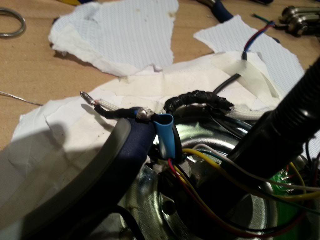
Gotta start somewhere - 1st phase wire furthest from the cable entry to get things underway. The wire ends are just loosely twisted here, but you can see the double-shrinkwrap on the end being joined :


One thing I've learned is that sometimes a decent blob of solder joining 2 short wires makes it impossible to get even the next 2 sizes up of shrinkwrap to fit over the join. You can take excess solder off up to a point but you sometimes get big bulges especially if you tin the wires first before splicing.

If the smaller one shrinks prematurely with heat due to wires being short during the job, the bigger one usually works to cover the solder join and compresses to the one beneath. Otherwise, you need to start over - or rely on self-fusing silicone tape. But I'd rather use than as an extra layer rather than the only insulation, especially in something rotating at 270rpm. Every wire was extremely well insulated on this motor so figured I'd put it back at least as well as I found it.

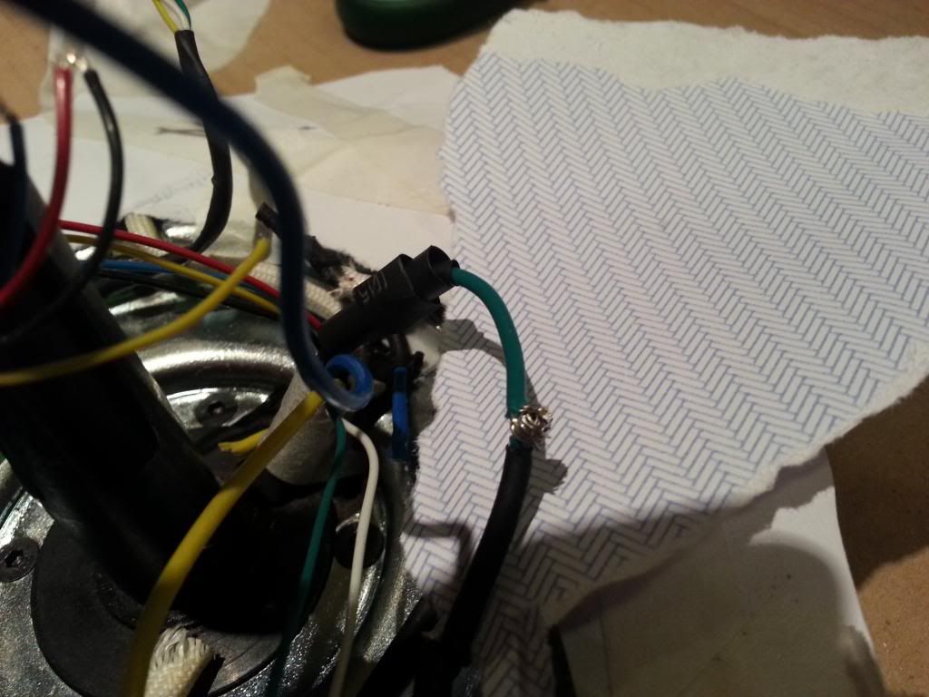
Next the blue phase wire - lifted up with a pair of plier handles to show the join better :


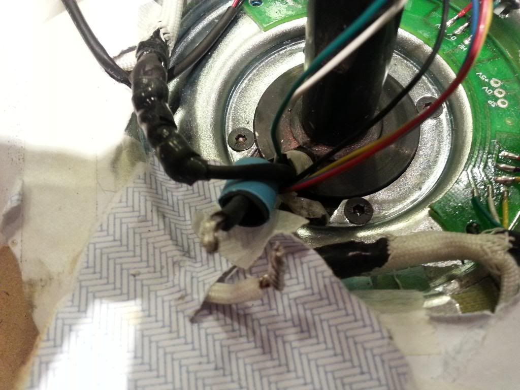
I was more confident by the yellow - and desoldered / resoldered the join at the copper wire :


All 3 phase wires replaced or spliced - The original and replacement sensor wires are taped down to the top of the torn up envelope which makes the "sheet" protecting the copper wound below from mishap, and are next on the list :


shemozzle999

Esteemed Pedelecer
Sep 28, 2009
2,826
686
I think they just wire in another standard hall sensor with the sensing face pointing towards the motor side plate and fit a magnet onto the side plate so you get a 1 pulse for every revolution of the wheel.

Check to see if they have already machined in a recess in the side plate to accept a small disc magnet which would align with the hall device if installed on the exposed pcb.

If my Chinese contact was allowed posting status on this forum I am sure she could give you a better answer but despite emailing Russ and RichardB asking on her behalf why she can not post here I have failed to get any response.
 

103Alex1

Esteemed Pedelecer
Sep 29, 2012
2,228
67
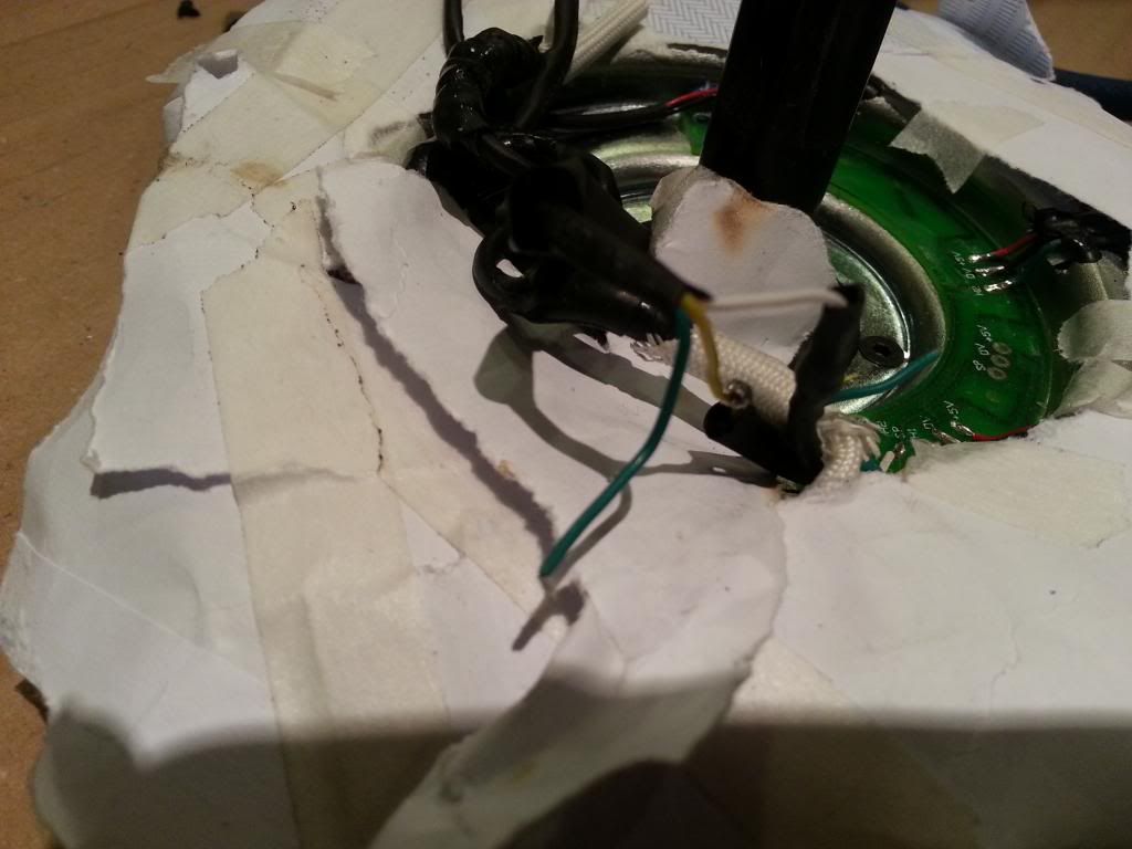
The sensor wires were spliced and individually shrinkwrapped to ensure no contact between the solder joins :


All ready for the final shrinkwrap to be pulled up and over the 3 joins to keep the bundle together :


The black, red and blue bundle was done exactly the same way on the other side this afternoon :