Project: ghEttoBIKE

jerrysimon

Esteemed Pedelecer
Aug 27, 2009
3,292
112
Cambridge, UK
Neptune good job and nice to see someone helping out a new member. One of my controllers also has a two wire 36v power supply though your "guess" seems accurate. Certainly power red +ve black -ve label 7 and motor wise label 1 yellow, blue, green. It seems clear the three wire label 4 connector is probably throttle or pedelec sensor as you say.

I also concur 5 & 6 look like cutout brakes.

As you say 2 & 3 are the unknowns.

Powering it at 24v will certainly not harm it whereas trying it at 36v could so best to try 24v first.

Regards

Jerry
 
Last edited:

jhruk

Esteemed Pedelecer
May 13, 2009
318
68
Hi Dan,

Looking at your controller diagram my first thoughts are that (4) is the pedal sensor, (5) & (6) brake cut outs, leaving (2) or (3) as the throttle with a voltage display or switch attached. Of course I could be completely wrong, and it does leave the question of the remaining half of (2) or (3). Speed control?

In the absence of anyone knowing this controller I think the first thing I’d do is connect the power leads (7) to a 24v battery, through a fuse as Neptune said.

I would then measure the voltage between the –ve battery lead and all of the leads (except the motor) in all the connectors - and make a note of any readings.

If you get 4-5v on any then we know the controller has power and no on/off switch connection.
If you get 4-5v on any and 24v on one then the 24v connector will probably go to a battery voltage indicator - which could be on the throttle.
If you get 24v on one but no other readings it might indicate there is a controller power switch on that connector.

If you get no readings at all it would suggest the controller is u/s.

I would then disconnect the battery and check for continuity between the –ve battery lead and the all the other leads. I would expect near zero resistance on all the black leads but high on most, but not all, of the others. Again make a note (low-high) of your readings.

This doesn’t identify the throttle lead yet, but at least it’s a start and gives us something to work on.
 
Last edited:

danielrlee

Esteemed Pedelecer
May 27, 2012
1,396
725
Westbury, Wiltshire
torquetech.co.uk
Thanks guys. I'm fairly confident that with your help, I'm going to be able to crack this controller. I've just ordered an inline blade fuse holder and some 12AWG wire. When it arrives I'll carry out some tests as suggested here and let you know my findings.

One last question for now: Would I be able to mount the wheel in a vise for testing purposes? I haven't got a clue how much torque this thing produces.
 

neptune

Esteemed Pedelecer
Jan 30, 2012
1,743
353
Boston lincs
I would not recommend mounting it in a vise. When doing tests, you are likely to trigger is suddenly into full throttle mode, and it could just leap out of the vise, causing damage to the axle threads , and to your good self. These things have an awful lot of starting torque. Temporarily mount it in the rear of any size bike frame you have available, and make sure the wheel nuts are tight[but not overtight].
On reflection, I am almost certain that your controller is the correct type. If it was made for a hall sensor motor, it would have one plug with a group of 5 wires for the hall sensors, and it does not.
Here is a question for other members. Is the ignition switch always connected to the controller, or is it , in some cases, just wired into the positive battery lead? If the latter is the case, it would make it easier to sus out this controller.
 

jhruk

Esteemed Pedelecer
May 13, 2009
318
68
Here is a question for other members. Is the ignition switch always connected to the controller, or is it , in some cases, just wired into the positive battery lead? If the latter is the case, it would make it easier to sus out this controller.
There will usually be a main isolating switch between the battery and controller, or sometimes in the battery itself. However some bikes will also have an on/off switch on the handlebar and this usually just switches the low voltage supply in the controller. This doesn’t require much current and enables you to turn the controller on/off with a much smaller switch and cable.
 
Last edited:

jerrysimon

Esteemed Pedelecer
Aug 27, 2009
3,292
112
Cambridge, UK
However some bikes will also have an on/off switch on the handlebar and this usually just switches the low voltage supply in the controller. This doesn’t require much current and enables you to turn the controller on/off with a much smaller switch and cable.
I use that function on most of my conversions now.


Regards

Jerry
 
Last edited:

danielrlee

Esteemed Pedelecer
May 27, 2012
1,396
725
Westbury, Wiltshire
torquetech.co.uk
Thinking ahead to mounting the wheel on a frame, I measured the necessary dropout width and was surprised to find out that it is a rather large 155mm. Assuming I have measured it correctly (smallest freewheel sprocket to securing nut on opposite end of axle) I am going to have to stretch standard frame dropouts (135mm) by about 20mm. Having looked into the various methods of doing this (threaded rod and nuts, inverted trigger cramp, foot and hand with brute force etc...) is there a general consensus on the best way to do it? Is it just a matter of trial-and-error? I haven't chosen the exact frame yet, so don't know the material I will be dealing with. Worst case scenario - Is 20mm too much to spread the dropouts of an aluminium frame?
 

flecc

Member
Oct 25, 2006
53,361
30,710
Is 20mm too much to spread the dropouts of an aluminium frame?
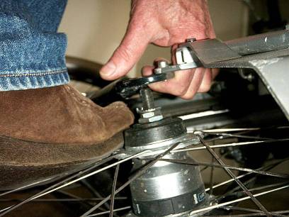
It's impossible to be certain for every frame type, but I've found this is acceptable on a 26" wheel frame. Here's an example of me changing a tube on an alloy Giant Lafree frame using hand and foot to expand it temporarily by about 25 mm:


And below is an example of a 20" wheel alloy frame permanently expanded by about 30 mm where it was necessary to separate the frame welds and re-weld afterwards, plus increasing the tube curves to return the dropout plates to parallel:


Attachments

Last edited:

jerrysimon

Esteemed Pedelecer
Aug 27, 2009
3,292
112
Cambridge, UK
plus increasing the tube curves to return the dropout plates to parallel:
As stated this becomes a problem the wider you spread the forks.

PS Flecc I love the foot on the hub to steady the wheel as the fork arm is yanked up lol

Regards

Jerry
 

flecc

Member
Oct 25, 2006
53,361
30,710
PS Flecc I love the foot on the hub to steady the wheel as the fork arm is yanked up lol

Regards

Jerry
I rarely bother to take out a back wheel for a tube or tyre change, indeed I fitted the very thick Marathon Plus tyre on that bike without taking out the back wheel, using that foot method. This is a legacy of my early trade days when a number of bikes had full chaincases, often oilbath types, and these were a nightmare for getting out back wheels. In those days bike frame expanders were a normal cycle trade tool sold by factors such as Brown Brothers Ltd* and we only took out back wheels on single speed bikes normally.

* Only motor factors now, such has been the takeover of the car.
 

danielrlee

Esteemed Pedelecer
May 27, 2012
1,396
725
Westbury, Wiltshire
torquetech.co.uk
Hi all.

I should be taking receipt of the bike tomorrow (Raleigh Avalanche - don't laugh though, this is the ghEttoBIKE ;)), but in the meantime I've carried out a few tests on the controller with 24v.

A reminder of the controller leads:

IMG_4681.jpg

First test - Ground continuity. All black wires have been confirmed as ground along with the yellow wires of 5 & 6 (suspected brake cutouts).

Second test - Pin Voltages. The red wire on plug 2 and the yellow wire on plug 3 both show 24v. The white wires on 5 & 6 both show 0.06v. All others show nothing.

Does this help anybody's theory? I think I'm in agreement that 5 & 6 are brake cutouts due to the low voltage shown. Seeing that there are no 4-5v pins yet, should I now try shorting the brake cutouts?

Obvious note: As ever, the fuse proved worthwhile as I have already blown one whilst probing with my multimeter :) (although I played it extra safe with a 5A one). Hopefully I haven't busted the controller. Values are still reading as above.

I think it might be a whole lot easier if I just replace the controller, although I'd rather not have to wait for shipping from the Far-East.....
 
Last edited:

danielrlee

Esteemed Pedelecer
May 27, 2012
1,396
725
Westbury, Wiltshire
torquetech.co.uk
Last edited:

jhruk

Esteemed Pedelecer
May 13, 2009
318
68
Ok …Obviously not powered yet. It looks to me as though it has a handlebar control with on/off switch connected to 2 or 3. The problem now is will it work without this control and, if so, which is the return wire.

I quite agree that it would be a lot easier to get a new one with known connections. However, if you want to proceed trying with this one perhaps you could remove the circuit board from the case and post some photos. They might give us some more clues.
 

danielrlee

Esteemed Pedelecer
May 27, 2012
1,396
725
Westbury, Wiltshire
torquetech.co.uk
Got the bike yesterday and spent hours cleaning, lubing and adjusting absoloutely everything I could think of. I took it for a ride through a few miles of chalenging terrain (for me at least) through Epping Forest this morning and what a blast! I havent rode for about 13 years and the first thing I noticed is how unfit I actually am :confused:

The second thing I noticed is how tight everything feels on the bike. Considering the state it was in when I collected it (stored outside for the last year), it rides well following my tinkering. It's lighter than I thought it would be and feels pretty solid. It was quite muddy out and in hindsight I should have taken a few photos to post before riding it. I'll do so after cleaning it in a bit.

Things aren't going so rosy regarding the controller though. I've decided to give up with it and buy a new one, along with throttle and peddle sensor from the same supplier to ensure no compatibility problems. I have eyed up the following on ebay from a UK seller. Any thoughts on these components? As far as I can see I shouldn't experience any issues for use with my motor.

ELECTRIC BIKE CONTROLLER 250W 24V 15A- SENSORLESS & HALL SENSOR COMPATIBLE | eBay

ELECTRIC BIKE E BIKE HALL THROTTLE 24V 36V COMPATIBLE | eBay

ELECTRIC BIKE PEDAL ASSIST SENSOR (PAS) FOR 24V OR 36 V SYSTEMS | eBay
 

danielrlee

Esteemed Pedelecer
May 27, 2012
1,396
725
Westbury, Wiltshire
torquetech.co.uk
I took the plunge and ordered the items listed in the previous post. They should be here towards the end of the week. Now I'm really excited about the possibility of having my electric bike up and running next weekend :)
 

jhruk

Esteemed Pedelecer
May 13, 2009
318
68
Those parts look fine to me – and not overpriced.

Look forward to hearing how it works.
 

danielrlee

Esteemed Pedelecer
May 27, 2012
1,396
725
Westbury, Wiltshire
torquetech.co.uk
I took a trip to the post office this morning to collect some goodies; a new controller, throttle and PAS sensor:

IMG_4695.jpg

Work never went as slowly as I couldn't wait to get home and make some serious headway on the ghEttoBIKE :)

I removed the old wheel and moved the 5 speed freewheel onto the hub motor wheel (might upgrade the gearing and shifter at a later date). I was surprised at how easy it was to spread the dropouts with some good ol' fashioned brute force. Using my foot for leverage, it didn't take much effort to pull them apart the required amount. The new wheel slotted in nicely and was flush with the frame with a few blows with a rubber mallet. Finally i tightened the axle nuts (BTW, can anyone tell me how much torque should be applied?)

Next I hooked up the controller to the motor and wired up the throttle. I chose a 10 amp fuse for the battery, crossed my fingers and plugged it in to the controller.

IMG_4697.jpg

No smoke or funny smells - always a good start. Picking up the throttle, I prayed, twisted it........ and got some movement, but it's clearly not what it should be. The motor clicks several times, then stops. During this clicking, the wheel may rotate randomly as each click occurs. Is this a phase issue?

When I repaired the motor last week, I couldn't find the correct coloured wire, so used a thick 3 core mains cable. I'm pretty sure that I haven't got the wires muddled up in reference to their new colours, but I guess I could have. I want to just swap them over at the controller to try an alternative phasing, but obviously don't want to damage anything if it's already wired in correctly. Is it okay to do this?
 
Last edited: