Not sure if this is in the right section

Scunnybuddy

Finding my (electric) wheels
Mar 24, 2025
7
1
Hi all I have brought my self a Lectro EM600 which was faulty when I brought it. I have done diagnostics on it and narrowed it down to the module. I have brought one off Amazon as per picture. I have wired it up as good as I can I have power to the display but no output from my pedal sensor (but didnt have any before). I not sure how to test the hall sensor. I don't have any power going to the motor. Any help would be much appreciated in wiring it up to my existing wiring. It is asking me for magnets etc. Many thanks

Craig


62477
 

thelarkbox

Esteemed Pedelecer
Aug 23, 2023
1,430
445
oxon
Testing the hall sensor for a cadence sensor is pretty straight forward.
if connected with the same plugs /sockets as pictured - you got the easy to test connector option.

use a multi meter to confirm the sensor is recieving 5v power and identify the +5v, Ground(-ve). and output pins. using the black probe on the ground pin and the red probe on the output pin rotate the crank and your meter should show a fluctuating reading between 0 and 4.5v if the sensor is reading ok.

If not check the distance from the sensor and the magnet ring if a 2 part sensor ensure its close and straight and test again.

Does your controller need configuration or self learning perhaps?
 

saneagle

Esteemed Pedelecer
Oct 10, 2010
7,762
3,586
Telford
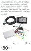
Here's how to test an ebike:
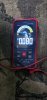
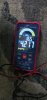
1. Measure the voltage at controller's battery connector. Obviously should be battery voltage. 36v - 42v for a 36v battery would be an acceptable range, but if you've fully charged the battery and it's less than 41v, it needs some sorting.
2. Measure the voltage on the 5v rail. You can measure that between any ground (black) and any of the reds going to throttle, PAS or motor halls. It should be around 5v.
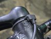
3. If you have a throttle, check throttle signal wire voltage on it's connector while connected. it's the wire that's not red or black on the throttle connector. Should give about 1v to 4v when you twist the throttle. If there's more than one wire, your meter will find it. It's the one that's between 1v and 4v, assuming that it works.
4. Check that the pedal assist sensor is pulsing. Measure the PAS signal wire while turning the pedals slowly. Should pulse 5v on and off every time a magnet passes the sensor. The signal wire is the one that's not red or black.
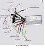
5. Check the motor hall signal wires (blue green and yellow) on the motor connector at the controller. They should each pulse with 5v going on and off as you rotate the wheel BACKWARDS. The controller must be powered for that test.
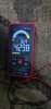
6. Mosfet test. Disconnect the motor cable and battery from the controller. Measure the resistance (200k scale) between the red battery connection and each of the three phase wire connections, then repeat with the black battery wire. Each set of 3 readings should be the same as each other and in the range 7K -24K. Though can be higher as long as they're all the same. Due to the capacitor across the battery wire, you can get a constantantly changing measurement while it charges. In that case, try swapping your probes round. Even though can be a moving result, the only important thing is that all three move in a similar way.

To test whether it's working, you should disconnect everything that's not needed, like Pedal sensor, lights and brakes. Listen for a tick or click from the motor when you operate the throttle, which indicates incorrect timing of the power pulses caused by incorrect connection sequence or faulty connection in the motor cable.

If your bike passes all those tests, it should work, so then you can look at any settings or other logical causes, like stuck brake switches, PAS installed backwards.
 

Scunnybuddy

Finding my (electric) wheels
Mar 24, 2025
7
1
Many many thanks for your reply. I will try these as soon as I finish work today. Again many thanks.
 

Scunnybuddy

Finding my (electric) wheels
Mar 24, 2025
7
1
Good evening all I have just tested the hall sensor which i have now cleaned up. I have got 4.29volts from the pins red and black 0.08volts between black and blue and again 4.27volts between red and blue nothing is switching or fluctuating or anything. Any other ideas?62489624926249362491
 

Scunnybuddy

Finding my (electric) wheels
Mar 24, 2025
7
1
I have also just tried dabbing a magnet on top of the sensor to see if that does anything but still nothing.
 

matthewslack

Esteemed Pedelecer
Nov 26, 2021
2,327
1,581
Move a magnet past the sensor in the direction, position and distance it expects. Try both poles, both directions. If there is an led on the sensor, it should flash.

Digital meters don't always sample fast enough to detect the pulse.
 
  • Like
Reactions: Scunnybuddy

thelarkbox

Esteemed Pedelecer
Aug 23, 2023
1,430
445
oxon
thats a 12x magnet sensor iirc so every '5 minutes' of rotation should illicit a response if measured between black/blue, try turning the crank slower - also check your meter manual for the feature behind that max/min button.. seems like that might be ideal for this situation??
 

saneagle

Esteemed Pedelecer
Oct 10, 2010
7,762
3,586
Telford
I have also just tried dabbing a magnet on top of the sensor to see if that does anything but still nothing.
It needs to be connected to and powered by the controller to switch. Is that how you're testing it? If you are doing it like that, have a look to see whether the centre part is actually rotating with the pedals.