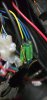
OK, we're getting somewhere now. That means the controller is switched on. You can forget about all these tests now because you said that the motor turns when you do the self-learning. That eliminates any problems with the motor or hall sensors.
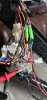
Do the self-learning test again until the wheel turns slowly forward, then switch off and disconnect the self-learning wires from each other.
Switch on again and test with a throttle, making sure that the red wire goes to red on the controller side, black goes to black and whatever the other colour is goes to whatever's on the other side. If you don't have a throttle, you can simply bridge the red wire to the white one on the throttle connector. Make sure the wheel is off the ground when you do that because it should make it spin, and make sure that you don't have level zero selected on the LCD. When you've done all that, report back.