Think i might need talking down..

guerney

Esteemed Pedelecer
Sep 7, 2021
11,363
3,226
No

I think many of the scopes of the kind you linked has STM32 as it's processor and there are few open source DIY scope projects using STM32 boards
According to the Neoteck DVM, the AN8008 generates pulses with about 50% duty cycle regardless of frequency, and I can't see if they're sine or square... so I might buy one of those cheapo amazon jobbies just out of curiosity. Or I could simply read the manual.

EDIT: Ordered it because the suspense is killing me, and it could be useful when attempting to repair things. Hope they don't just send me the probe at that price lol - it was about three times the price on AliExpress when VAT and delivery was added. If nothing else it'll be a second spare cheap DVM, currently of unknown accuracy.


55545
 
Last edited:
  • Like
Reactions: afzal

guerney

Esteemed Pedelecer
Sep 7, 2021
11,363
3,226
@afzal: I knew it was too cheap, on AliExpress that's the price for just the probe - the Amazon seller has just now cancelled my sillily priced sillyscope/oscilloscope order. I'll raise a very disappointed and angry sounding complaint, try to get an Amazon voucher... this sometimes works.
 
Last edited:

afzal

Pedelecer
Mar 26, 2023
48
21
Kerala, India
DS211/DS212 looks similar to that, but it costs similar to PC based scope.

There are DSO138 available here, cost when translated would be around 15 quid

Note: I have used none of the above (EDIT: except PC based scope)

With a true rms multimeter, it would have been possible to figure out whether the waveform is sinusoidal or square (on the basis of rms/average), but looks like your Neoteck DVM isn't true rms (else it would have been advertised loud)
 
Last edited:

guerney

Esteemed Pedelecer
Sep 7, 2021
11,363
3,226
DS211/DS212 looks similar to that, but it costs similar to PC based scope.

There are DSO138 available here, cost when translated would be around 15 quid

Note: I have used none of the above (EDIT: except PC based scope)

With a true rms multimeter, it would have been possible to figure out whether the waveform is sinusoidal or square (on the basis of rms/average), but looks like your Neoteck DVM isn't true rms (else it would have been advertised loud)
For me at least, the answer to this question is worth much less than £15. On the other hand, answering other questions in future using an oscilloscope could be worth more.

The measured voltage readbout on the Neoteck display doesn't step between 0V and 4V, instead it's various voltages in between and 0V, therefore the signal could be sinusoidal? To show you the rapidly changing detected voltage, I would have to record the voltages and upload framegrabs (or the readings from those frames), from a video recording. With a very high framerate on my GoPro, time between reading changes could be determined.


55595


55596
 
Last edited:

afzal

Pedelecer
Mar 26, 2023
48
21
Kerala, India
The measured voltage readbout on the Neoteck display doesn't step between 0V and 4V, instead it's various voltages in between and 0V, therefore the signal could be sinusoidal? To show you the rapidly changing detected voltage, I would have to record the voltages and upload framegrabs (or the readings from those frames), from a video recording. With a very high framerate on my GoPro, time between reading changes could be determined.
I don't think it is possible to determine sine vs square observing the meter variations. There is a lag in calculating/displaying the average value, with a low frequency it would keep on varying and it can't reach either peaks (0 & 4V). And if a high frequency signal is fed, I expect the average value to be 2V for both square & sine.

Okay, I looked up further up this thread & the other thread "Checking Multimeter Calibration at Home". So you have two multimeters, Neoteck DM4000 Pro & ANENG AN8008. And you are trying to find whether signal generated by ANENG AN8008 is square/sin. If going by ANENG AN8008 photo, it should provide square wave.
ANENG AN8008 is a true rms meter, but signal generated can't be back fed to itself to determine sin vs square by rms/average value, while Neoteck DM4000 Pro is not a true rms meter.
 
  • Like
Reactions: guerney

afzal

Pedelecer
Mar 26, 2023
48
21
Kerala, India
I think component soldering would be required with the above

This probably is in essence same as above, but with components assembled & enclosure

Note that it is single channel only
 

guerney

Esteemed Pedelecer
Sep 7, 2021
11,363
3,226
I think component soldering would be required with the above
Appears to be assembled or DIY? Pay an extra 14p to make child factory slaves earn their keep.

55626

55627
 
Last edited:

thelarkbox

Esteemed Pedelecer
Aug 23, 2023
1,205
365
oxon
I may have stalled/paused this project but its not forgotten.

I hit a bit of a snag with the initial plan as branching off the main battery feed proved tricky with the in sled controller set up, leading me to consider a secondary independent battery supply for the lights etc.
Also providing the benefit of not reducing the bikes range under power.

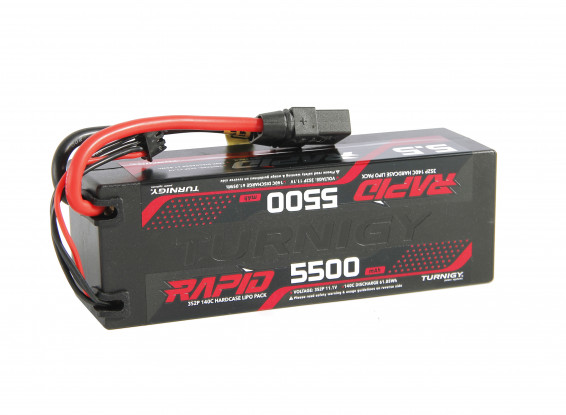
After a long period of cogitation and browsing around on the subject i landed on 3s2p lipo packs to provide an initial circa 12v supply from which i can step down for both dim lighting and logic /switching circuits. Ive already tested the leds at circa 14v in error while connecting up to the psu set a tad high ;)


I cant help wonder if 3x in a 3p setup would provide a usable backup for the drive battery.. Not a plan just a thought..
 

saneagle

Esteemed Pedelecer
Oct 10, 2010
6,798
3,133
Telford
I may have stalled/paused this project but its not forgotten.

I hit a bit of a snag with the initial plan as branching off the main battery feed proved tricky with the in sled controller set up, leading me to consider a secondary independent battery supply for the lights etc.
Also providing the benefit of not reducing the bikes range under power.

After a long period of cogitation and browsing around on the subject i landed on 3s2p lipo packs to provide an initial circa 12v supply from which i can step down for both dim lighting and logic /switching circuits. Ive already tested the leds at circa 14v in error while connecting up to the psu set a tad high ;)


I cant help wonder if 3x in a 3p setup would provide a usable backup for the drive battery.. Not a plan just a thought..
Don't forget that you need low voltage cut-off with a lipo because there's no BMS. Alternatively, use a lipo alarm.
 

guerney

Esteemed Pedelecer
Sep 7, 2021
11,363
3,226
I wouldn't want to be relying on indicators which might wink out with a depleted battery - can't you just splice in a "Y" between your ebike battery and controller?
 

thelarkbox

Esteemed Pedelecer
Aug 23, 2023
1,205
365
oxon
Don't forget that you need low voltage cut-off with a lipo because there's no BMS. Alternatively, use a lipo alarm.
Cheers and Yes thats covered with avoltmeter, though a lipo alarm could be useful in addition just in case i dont look/check.. @guerney its do-able but would involve significant plastic surgery and compromising isolation and waterproofing measures. every time i unhook it open up and have a look see its been a few times now.. its a guttural and very negative response telling me 'nah!' then the number of leds is such that even driven at a lower voltage a significant drain will be demanded and i dont want to rob amps from my drive battery,
 

AntonyC

Esteemed Pedelecer
Apr 5, 2022
330
143
Surrey
"i may have both 36 and 48v batteries".... you'd need 55V to 29V. Woosh suggested this style and it's been reliable in all weather:
48V/60V(10V~60V) to DC5V 10A 50W Waterproof Power Converter Regulator

Are you sure the controller won't come out of the sled and expose a take-off point near the battery pins?

For less battery drain low power concentrated in a small area gives high brightness, a typical rear light uses up to 0.5W. How about a short bright strip by day and longer but dimmer by night?

Apparently hot glue or epoxy resist weather better than nail polish. (Who's been spending too long on Youtube?)
 

guerney

Esteemed Pedelecer
Sep 7, 2021
11,363
3,226
For my lights, I simply cut the cable between the controller and the 19.2Ah battery, made two "Y" junctions, soldered on an inline blase fuse... and weatherproofed using self-adhesive 4:1 heat shrink and self-amalgamating rubber tape. I might solder this on for indicators if I need 12V, and ever get around to making them, if I decide to make them.

56179


"i may have both 36 and 48v batteries".... you'd need 55V to 29V. Woosh suggested this style and it's been reliable in all weather:
48V/60V(10V~60V) to DC5V 10A 50W Waterproof Power Converter Regulator
Good to know! Was wondering.
 

thelarkbox

Esteemed Pedelecer
Aug 23, 2023
1,205
365
oxon
Thanks for the pointer/link @AntonyC ive got a small 1 or 2a constant voltage converter thats sufficcient to power the switchset and relays, the switchset is wired with the thinnest wires drive 2-3a of leds through them and it will tun into a short lived hand warmer i suspect
 

thelarkbox

Esteemed Pedelecer
Aug 23, 2023
1,205
365
oxon
@guerney Some solid potting compound seals the rear of the battery socket and controller pcb connections, and the enclosure fits together with steel 'guillotines' to chop/cut into any unexpected wires in the cramped space housing hot pcb components clamped to a steel base plate. not a luishi controller but another brand and its not like any pics i found online before with exposed wires connecting to the pcb from the battery socket..

It could be done but would be more destructive than is comfortable chopping off obstructing steel structure, MIght not be steel might be an alloy, I am currently relying on recall sat in the house warm ;) If it were simply solder in a couple of wires and route through to an exit point it would have been done when i first cracked the case late summer/early autumn.

I did consider a rip out and replace with a KT controller until i discovered the insled controllers dont have the dual voltage feature allowing he 'safer' overvolting of the motor and using my 48v battery if needed for range/distance. A very significant benefit of the controller upgrade imho.

And so far none of the other benefits of a kt controller justify hanging a further box on the bike to house a controller and housing a replacement controller with the lighting additions will hamper the 'easy' switching between bikes, ...

with the battery and relays etc for the lighting system which is mounted on or too the boxes front and rear
all housed under a false bottom made from a second box stacked into the first at the rear.

So to swap between bikes it should be as simple as disconnecting the switchset, sniping the cable ties securing the switchset cable the cable between the 2 boxes and the boxes themselves. , then reversing the procedure on the alternative bike (with suitable racks front and rear..)
 

Nealh

Esteemed Pedelecer
Aug 7, 2014
20,917
8,533
61
West Sx RH
The lipo bricks were yeterday's news.
One needs a dedicated lipo charger and alarms set to min 3.6/3.65v as they soon fall off the cliff edge .
The 9p solution is highly flawed and next to useless, 37.8v max charge only gives one a marginal usage before the alarms will sound. With voltage sag they will be even worse.
 
  • Informative
Reactions: thelarkbox

AntonyC

Esteemed Pedelecer
Apr 5, 2022
330
143
Surrey
Some solid potting compound seals the rear of the battery socket and controller pcb connections, and the enclosure fits together with steel 'guillotines' to chop/cut into any unexpected wires in the cramped space housing hot pcb components clamped to a steel base plate.
Piccy? Heard and believed but still curious.
 

thelarkbox

Esteemed Pedelecer
Aug 23, 2023
1,205
365
oxon
Piccy? Heard and believed but still curious.
next time im pottering in the garage at a loose end, or have other reason to open will do. tho i will admit to straying into poetic license when using the guillotine reference ;) not on the gunk ..
 
  • Like
Reactions: AntonyC