I can't agree more. However, this thread appeals to the tinkerers among us. Although I would not advocate for paralleling batteries, I am still curious to understand the risks involved.Just beacause it has worked doesn't make it inherently safe , the individual has no idea of what is occurring with the BMS and later on risks issues and fires if critical components on the BMS are damaged irreversibly.
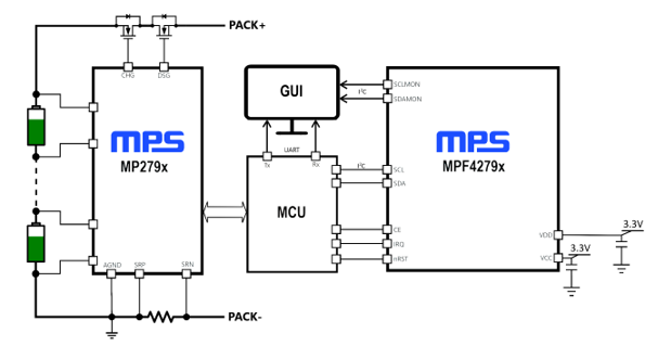
This is a reference BMS for up to 16 cells in series, it's kind of typical for modern BMSes:

QUOTE:
This board uses the MP279x ICs, a robust family of battery management analog front-ends (AFEs) that provide a complete AFE monitoring and protection solution. The MP279x supports up to 16 cells in series, and provides two separate analog-to-digital converters (ADCs) for synchronous voltage and current measurements. The high-side MOSFET (HS-FET) driver and robust HW protection functions come with configurable thresholds. Protections include over-current protection (OCP), short-circuit protection (SCP), battery and cell over-voltage protection (OVP), battery and cell under-voltage protection (UVP), over-temperature protection (OTP), and under-temperature protection (UTP). The MP279x also integrates internal balancing FETs to equalize mismatched cells while offering the option to control external FETs for a higher balancing current.
/QUOTE
The BMS of the passively charged battery would still monitor the cell pack even when charged through the output and switch off its output FETs (on the pack+), stopping the process... or wouldn't it?
Note: this particular reference design has two inline FETs on the pack+ line so would have prevented charging by the output port.
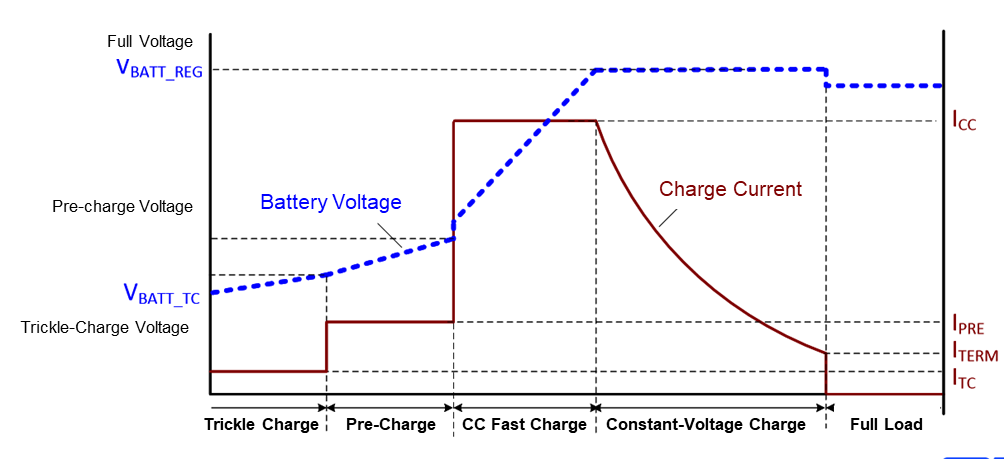
On the charger side, a reference on the different stages of charging:

Last edited:


