Supplementary Battery Question

Woosh

Trade Member
May 19, 2012
20,582
16,990
Southend on Sea
wooshbikes.co.uk
Just beacause it has worked doesn't make it inherently safe , the individual has no idea of what is occurring with the BMS and later on risks issues and fires if critical components on the BMS are damaged irreversibly.
I can't agree more. However, this thread appeals to the tinkerers among us. Although I would not advocate for paralleling batteries, I am still curious to understand the risks involved.

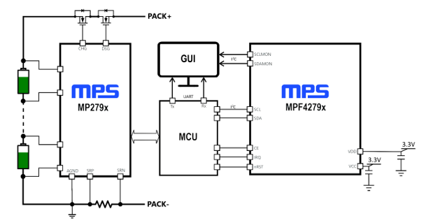
This is a reference BMS for up to 16 cells in series, it's kind of typical for modern BMSes:


QUOTE:

This board uses the MP279x ICs, a robust family of battery management analog front-ends (AFEs) that provide a complete AFE monitoring and protection solution. The MP279x supports up to 16 cells in series, and provides two separate analog-to-digital converters (ADCs) for synchronous voltage and current measurements. The high-side MOSFET (HS-FET) driver and robust HW protection functions come with configurable thresholds. Protections include over-current protection (OCP), short-circuit protection (SCP), battery and cell over-voltage protection (OVP), battery and cell under-voltage protection (UVP), over-temperature protection (OTP), and under-temperature protection (UTP). The MP279x also integrates internal balancing FETs to equalize mismatched cells while offering the option to control external FETs for a higher balancing current.

/QUOTE

The BMS of the passively charged battery would still monitor the cell pack even when charged through the output and switch off its output FETs (on the pack+), stopping the process... or wouldn't it?
Note: this particular reference design has two inline FETs on the pack+ line so would have prevented charging by the output port.

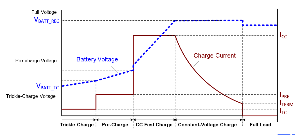
On the charger side, a reference on the different stages of charging:

 
Last edited:
  • Like
Reactions: Bikes4two

Bikes4two

Esteemed Pedelecer
Feb 21, 2020
1,037
445
Havant
There is an oscillation you get when you parallel a new battery with low internal resistance with an old battery with a higher internal resistance . The batteries may balance initially but what happens under load?
.............................................. etc etc
Thanks for your input @Sturmey and I understand what you are saying but I'm not sure if having two battery packs of different internal resistance is an issue for the two packs I'm using.

Both of my packs (a 2p and a 1p) are built of the same cells bought from the same supplier and within a few months of each other so it's a reasonable assumption they were manufactured around the same.

Anyway, in the ideal situation, I do indeed want the 2p pack to deliver twice the energy of the 1p pack and having now done two long rides (52 miles, 62 miles) with these packed parelled up, it looks as though (from using a coulomb meter on recharging) that this is the case.

What I don't know of course whether under riding conditions, is each battery pack delivering energy to the motor proportionally at the same time, or whether one pack is doing all the work and the second pack is topping up/equalising (oscillating to use your term).

As an aside, another poster on this thread thought that single port BMS were 'cheepo and crappy' - that may be the case but I've been using such devices (from 'BeMuchSafer' and as recommended by another esteemed battery build on this forum) for a few months now, and no problems so far, but if I do have issues I will of course share that experience on the forum.
 

Woosh

Trade Member
May 19, 2012
20,582
16,990
Southend on Sea
wooshbikes.co.uk
As an aside, another poster on this thread thought that single port BMS were 'cheepo and crappy' - that may be the case but I've been using such devices (from 'BeMuchSafer' and as recommended by another esteemed battery build on this forum) for a few months now, and no problems so far, but if I do have issues I will of course share that experience on the forum.
the key thing is to find out if you have back to back FETs on your battery packs. FETs conduct both ways because they have body-diodes but on a modern BMS (especially those small sized and without bleed resistors), it is usual to have back to back FETs like in the reference BMS circuitry I posted. If they have back to back FETs, the current flows only one way, out of the pack.
The simplest way to find out is to have a small difference in voltage between the two packs then connect them with your Y connector and leave it for 10-15 minutes. Remove the Y-connector and check if the difference disappears. Do that without the controller connected.
 

saneagle

Esteemed Pedelecer
Oct 10, 2010
7,253
3,355
Telford
the key thing is to find out if you have back to back FETs on your battery packs. FETs conduct both ways because they have body-diodes but on a modern BMS (especially those small sized and without bleed resistors), it is usual to have back to back FETs like in the reference BMS circuitry I posted. If they have back to back FETs, the current flows only one way, out of the pack.
The simplest way to find out is to have a small difference in voltage between the two packs then connect them with your Y connector and leave it for 10-15 minutes. Remove the Y-connector and check if the difference disappears. Do that without the controller connected.
Are you sure about that, or doing too much internet research? I've never found a battery without comms that didn't charge through the output, except when the mosfets were switched off. In other words, if you can measure normal voltage there, you can always charge there too. Check some of yours and let us know what you find.

That diagram you posted above doesn't look anything like your average Chinese BMS. Where did you get it from? I'm going to guess its from a solar or household battery system.
 
Last edited:

Woosh

Trade Member
May 19, 2012
20,582
16,990
Southend on Sea
wooshbikes.co.uk
That diagram you posted above doesn't look anything like your average Chinese BMS. Where did you get it from? I'm going to guess its from a solar or household battery system.
The picture is from https://www.monolithicpower.com/en/battery-management-system-solution-module

have you had one of those tiny BMSes? They run with just a couple of ICs and a couple of FETs.
Andy is on holiday, he'll be back on Monday. I'll ask him to take a picture for you.

edit:

They have similar schematics here:
How to design a battery management system - EDN

 
Last edited:

Bikes4two

Esteemed Pedelecer
Feb 21, 2020
1,037
445
Havant
  • Hi @Woosh - thanks for the info in post #43
  • So just got back from the bike shed where I measured my two 10s 1p battery packs and after discharging one for a little bit (and giving it recovery time), their terminal voltages were 41.4v (on the common port BMS, no balance system) and 40.7v on a dual port BMS with balancing system.
  • On paralleling up there was an intial current flow of 950mA which quickly decayed and after around 20 mins was less than 20mA
  • Disconnected the parallel arangement, waited 30 odd mins and re-checked the terminal voltages.
  • The common port battery was 41.0v and the dual port battery 40.9 v - this is using a fairly low grade DVM (I wish I could justify buying a Fluke :confused: )
So in terms of your post #43 (which I didn't follow 100%) are my BMS 'back to back FETs' or what?

Thanks.
 

Woosh

Trade Member
May 19, 2012
20,582
16,990
Southend on Sea
wooshbikes.co.uk
you have a traditional BMS, same as saneagle's. After an intial flow and the two packs arrived at more or less the same voltage after a while. If you have back to back FETs, there would not be an initial flow. Just to confirm, you measure the current flow between the two batteries, nothing to do with the controller?
 
  • Like
Reactions: Bikes4two

Bikes4two

Esteemed Pedelecer
Feb 21, 2020
1,037
445
Havant
........Just to confirm, you measure the current flow between the two batteries, nothing to do with the controller?
Yes I did thanks - I had both batteries on the bench and used the little test wiring jig I first showed in post #28 and confirmed the readings with a DVM. :cool:
 
  • Like
Reactions: Woosh

Sturmey

Esteemed Pedelecer
Jan 26, 2018
654
357
68
Ireland
........ BMS were 'cheepo and crappy' - that may be the case but I've been using such devices
There is an additional feature (hack) I always do to my own home brew batteries and sometimes other batteries and that's to fit an additional test wire so I can quickly manually monitor the batteries condition/balance without having to open the case.
This test wire consists of a connection to the balance wire between the fifth and sixth cell (10s 36v). The idea here is that we put a center tap on the battery. Regularly then, the voltages can be read between each pole of the battery and the center tap and compared. On cheap multi-meters with 2/20/200 scales, this needs to be done using the 20v scale when the battery is below 40v and not charging to get enough digits. The voltages are usually within .01 volt of one another.(e.g 19.83v on positive side, 19.82v on negative side) This could be considered as a sort of 'batch test' but it does put my mind at rest.
Anyhow, most internal battery faults (e.g self discharge, cell unbalance, low/high cell group etc) will show up on this additional test wire. I usually put some extra fibreglass sleeving on test wire and make sure it cant short with battery. A small 10K ohm resistor (sleeved) can be put in series between the test wire and 5/6 cell connection if you want absolute short circuit safety.
 
Last edited:
  • Like
Reactions: Woosh and Bikes4two

Bikes4two

Esteemed Pedelecer
Feb 21, 2020
1,037
445
Havant
  • Thanks @Sturmey - I like the 'centre tap wire' idea.
  • On one of the 1p batteries I built, I used a single port BMS without balance function but instead wired in a second 11-way JST XH connector so that (a) I could periodically monitor the balance condition of all the cells and (b) connect them up to an active balancer module should the need arise (an idea shared with me from @Nealh).
  • It was a bit of a task wiring up the extra JST connector along with the one that goes to the BMS, so the single 'centre tap wire' has its appeal.
  • Arguable of course, having the ability to balance without pack dis-assembly has its advantages, but how often/if/when it will be necessary to balance, I don't know.
 

harrys

Esteemed Pedelecer
Dec 1, 2016
367
101
74
Chicago, USA
There's a reason we don't charge batteries through the discharge port!
The reason is that the charge protection circuits are bypassed.

It was a combo of errors and oversights, but I once connected a 48V charger to the output of a 36V battery. Luckily, I alwsys check any charginging packs and unplug them before I go to bed, and I found this one around midnite, getting hot, Oh man, nothing to do but chuck it in a pail of water and some of the cell groups were still warm the next morning.