New Super Light Tongxin Motor Design/Kit

jerrysimon

Esteemed Pedelecer
Aug 27, 2009
3,292
112
Cambridge, UK
Just been out for another much longer ride, this time after fitting a cutout brake. The three mile ride included a few more hills/inclines. I am SO much happier and can really see now when pedelec comes into its own. For me having the cut out brake seem to makes it much more comfortable to ride. I think I will also wire a switch in on the same circuit, so I can switch the assistance on and off at will. I will post an update with a few more pics tomorrow.

The real test after the build is finished and it's all working, will be to see how it performs on my day to day commute in terms of being robust and reliable. In the meantime I won't be ditching my Nano motors until then!

Regards

Jerry
 
Last edited:

superDove

Pedelecer
Oct 24, 2011
193
35
Cheshunt, Herts. UK
Glad it's going well Jerry and that you're more comfortable with the pedelec function as well.

Well done for being one of the first to use this set up. The smaller motor seems to really suit the Brompton's form so much better.

I'm glad to hear the freewheeling is similar/same to the Nano as well.

Thanks for taking the time to update the thread I know I'm not alone when I say I'm very interested to see how you get on with this.

regards
James
 

jerrysimon

Esteemed Pedelecer
Aug 27, 2009
3,292
112
Cambridge, UK
Well maybe spoke to soon as have encountered a problem :(

Everything worked perfectly with the test rig both on the cycle stand and real riding, so I decided to solder it all up including fitting an umbilical to connect it all to the controller in the bag.

Anyway on the stand it all worked perfectly again the motor starting at low cadence and speeding up as I increased cadence, but under load when riding the motor cuts in and out as I start to cycle and stops. If I then continued to cycle at full speed it kicks in at full power but on stopping and initially starting again the same thing happens. I have checked the battery in fact tried two different ones and they are fully charged.

I have to say I am pretty confused. I hope the controller is not faulty and that somewhere in wiring up, I have a lose connection or a wire is shorting. Strange thing is at full cadence the motor assists and runs fine its only a slower speeds ?

Anyway pointers would be good ?

I am going to have to rip all the connections apart and try again sigh...


Regards

Jerry
 
Last edited:

laroche

Pedelecer
Apr 16, 2012
30
0
Jerry

Oops!

First thing that occurs to me is that infernal sensor and disk! Maybe the sensor is not picking up a signal from all the magnets. That would make it hesitant at slow cadences, but OK faster. So, is the distance between the sensor and disk constant at all points of the latter's rotation - even when under physical load? Is there any play in the axle? Is the disk firm and vertical on the axle - spinning true, as it were?

laroche
 

jerrysimon

Esteemed Pedelecer
Aug 27, 2009
3,292
112
Cambridge, UK
The disc/sensor are exactly as they were when I tested it for the first ride. Nothing has moved or broken lose.

Just been out on another ride. Its definitely a sensor issue. The only thing that has changed since my test ride is that I have extended the the sensor wire (its quite long) and I am wondering if by lengthening it I have messed with the sensor operation i.e. maybe the wire has to be a certain length/not too long ?

Its all very strange. When the motor finally kicks in at full power it is fine it is only when I slow the cadence down that it again loses its "sense" and effectively kicks in then turns off over and over again ?

PS I wonder if the wire I used to extend it is faulty. The wires were a little thicker maybe voltage drop is too large hmmmm

I am going to shorten it back to how it was and see what happens. Process of elimination I guess.

Regards

Jerry
 
Last edited:

jerrysimon

Esteemed Pedelecer
Aug 27, 2009
3,292
112
Cambridge, UK
Finally got to the bottom of it. I removed the extension and the new multi 7/8 way plug, (the Tongxin one we recently sourced through the forum) and connected it directly. Worked perfectly. I then added in the extension cable without the plug and it again worked perfectly which means the problem is in the plug. Very strange. Maybe the resistance in the larger plug pins (the connecting wires are tiny) messes with the sensor voltage or the plug itself is faulty. I expect the former given the fact it works but just not properly ?

Annoying as I spent hours soldering it all up and if a plug is going to mess it up, it may mean I have to fit the controller to the bike itself. I want to test/trial it with the supplied controller really and I suspect using another controller with the same sensor will result in the same problem. I may try it with throttle on another Tonxgin controller.

I am considering connecting a throttle to the same wires (all color coded the same) that the sensor connects to. Would that work, would I damage the controller ?

Should I measure the voltage on the wires first ?

Regards

Jerry
 
Last edited:

jerrysimon

Esteemed Pedelecer
Aug 27, 2009
3,292
112
Cambridge, UK
Well bit the bullet and tried a throttle on the same wires, red black white... zilch, nada, zero :(

So that rules that out! I plugged it all back in and it work fine with the pedelec, so nothing blown... phew.

I thought I would continue to be brave and plug it into one of my existing Tongxin controllers. No bleep from the motor when powered like the stock controller (I need to check again that the bleep does in fact come from the motor). Anyway good news is it works fine with throttle. Not certain but it seems to be a little rougher than through the stock controller though. May just me being nervous about using a different controller though.

I am going to fit the stock controller to the bike itself and use pedelec to try it out and about. If I hate it I will move to another Tongxin controller and use throttle.

The other motor with built in controller has a power step gizmo but that does not work with these motors with external controllers.

If nothing else I have learnt all about pedelec controls and the pros and cons.

Regards

Jerry
 

benjy_a

Esteemed Pedelecer
Jul 25, 2009
417
26
Would there be any advantage in fitting a custom programmable sensorleess controller? Could then have pedelec or throttle or both...

Ben
 

jerrysimon

Esteemed Pedelecer
Aug 27, 2009
3,292
112
Cambridge, UK
A few more pics to show how I fitted the disk and sensor.

The crank has a raised boss on it


So I hollowed out a bit of the ring so it would sit flush. The magnets are on the other side. The ring is quite wide so plenty of material left


Fitted with a tiny gap all round so it is not rubbing


.
 

jerrysimon

Esteemed Pedelecer
Aug 27, 2009
3,292
112
Cambridge, UK
I emailed Tongxin about how they recommend fitting the sensor. They sent these


Looks like they have a spacer under theirs.


Hmm just noticed they have their mounted on the non crank pedal, wonder if that makes a difference ?
 
Last edited:

jerrysimon

Esteemed Pedelecer
Aug 27, 2009
3,292
112
Cambridge, UK
My solution using five minute epoxy. Its very secure and I don't think it will be moving anytime soon :p


Gap set to about 2mm. The sensor lead is cable tied on the other side of the frame so it can't pull or snag.


It is at a slight angle (the the way the frame and weld sits underneath and needed trimming slightly) so might be why it starts the motor if you pedal back frantically ?


Regards

Jerry
 
Last edited:

neptune

Esteemed Pedelecer
Jan 30, 2012
1,743
353
Boston lincs
Jerry, here is my understanding of why you cannot connect a throttle in place of a pedalec sensor, and get results. Both a throttle and a sensor are hall effect devices. Think of a hall effect device as a variable resistor. It has three terminals, or wires going to it . Two of the wires supply power to it , usually red and black, positive and negative . Think of the third, or green wire as the output voltage wire. when the hall effect device is switched on by a magnetic field , you can measure a voltage between the green output wire , and the negative supply wire [black]. This voltage will be between 0 and 5 volts, depending on the strength and orientation of the magnetic field.
When we twist a throttle, we move a magnet in proximity to the hall sensor. Once we "set" the throttle, this voltage remains constant until we move the throttle again.
In the case of the sensor, the crankshaft moves the magnets, constantly switching the hall effect device on and off . So the voltage on its output wire constantly switches between 0volts and 5 volts, at a speed proportional to cadence. So to get your throttle to imitate a sensor, you would need to fully open and close it at a rate of about 8 times a second. I hope this helps you understand.
 

jerrysimon

Esteemed Pedelecer
Aug 27, 2009
3,292
112
Cambridge, UK
Thanks, so it would work but I would just need a bionic thumb and wiggle it like crazy :p

Regards

Jerry
 

benjy_a

Esteemed Pedelecer
Jul 25, 2009
417
26
It would really be a very basic (GCSE level) circuit to emulate this. Could be done with a few components mounted on a tiny PCB in a tiny box.

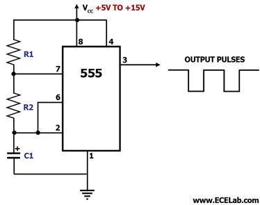
I remember making timer on/off circuits utilising an 8 pin chip called a 555 timer. From memory all you would need is that, a small capacitor and a variable resistor which would be your throttle. I'm sure there's not much else to it than that (trying to remember a circuit from 20 years ago!)

The output from the timer circuit would go to the pedelec input on the controller. The 555 timer emulates the pulses from the sensor.

In fact if I get the chance I'll try and make one and try it on my juicy bike controller for fun.

Ben
 

benjy_a

Esteemed Pedelecer
Jul 25, 2009
417
26
Here you go....just as I remembered! The two resistors shown can be replaced with a potentiometer (variable resistor) so only 3 components needed.


jerrysimon

Esteemed Pedelecer
Aug 27, 2009
3,292
112
Cambridge, UK
Thanks I might speak to the electronic engineers at work. I am pants at this stuff.

Regards

Jerry
 

neptune

Esteemed Pedelecer
Jan 30, 2012
1,743
353
Boston lincs
Hi Benjy_a. I did suggest this idea a while ago, but not having actually worked with 555 chips, I did not have a circuit diagram . An important question here is which resistor needs to be varied to change the pulse rate? Ideally we need to vary the pulse rate without changeing the mark/space ratio. It would be useful also to have values for R1, R2. and c1.
Another possibility would be to use the above circuit to drive a small electromagnet through a driver transistor . Although it would need a separate battery supply , it would have the advantage that you would not risk blowing up your controller, just place the electromagnet near your existing sensor.
 

benjy_a

Esteemed Pedelecer
Jul 25, 2009
417
26
Once you have a dabble it's really easy. You could get all the stuff you need from Maplin for a couple of quid. The only other thing you would need to do is check what voltage the pedelec sensor is working at (I guess 5V) and step down the voltage accordingly to the 555 timer. The circuit would run at 5V but any more than 15V will fry the 555 chip. You can buy something called a bread board to plug components into and have a play:

AD-100 Breadboard : Breadboards : Maplin Electronics

http://www.maplin.co.uk/ne555n-timer-2704

Ben
 

benjy_a

Esteemed Pedelecer
Jul 25, 2009
417
26
Hi Benjy_a. I did suggest this idea a while ago, but not having actually worked with 555 chips, I did not have a circuit diagram . An important question here is which resistor needs to be varied to change the pulse rate? Ideally we need to vary the pulse rate without changeing the mark/space ratio. It would be useful also to have values for R1, R2. and c1.
Another possibility would be to use the above circuit to drive a small electromagnet through a driver transistor . Although it would need a separate battery supply , it would have the advantage that you would not risk blowing up your controller, just place the electromagnet near your existing sensor.
Hi Neptune,
I will really have to go any revise how it works exactly. The two resistors when replaced with a potentiometer will both vary and the signal voltage will vary accordingly as you will have a 'potential difference' setup (again all from hazy memory).

The capacitor value plays a part in the pulse length as the 555 timer uses it's charge level to determine when it switches on and off. I don't think the circuit would need to be any more complicated than this to work.

I have an oscilloscope so will build a circuit and test. I have a cheap spare controller that I can try it on. There is little chance of frying the controller as long as the voltage is not high which I can check on the scope.

Ben
 

benjy_a

Esteemed Pedelecer
Jul 25, 2009
417
26
This may not work on sensors which expect an irregular pulse input...thinking about it don't most of the discs have irregularly spaced magnets and thus only work in one direction? This could be a fly in the ointment of the dastardly plan!!

I will wire up a pedelec sensor to the oscilloscope to see what it looks like.
 
Last edited: