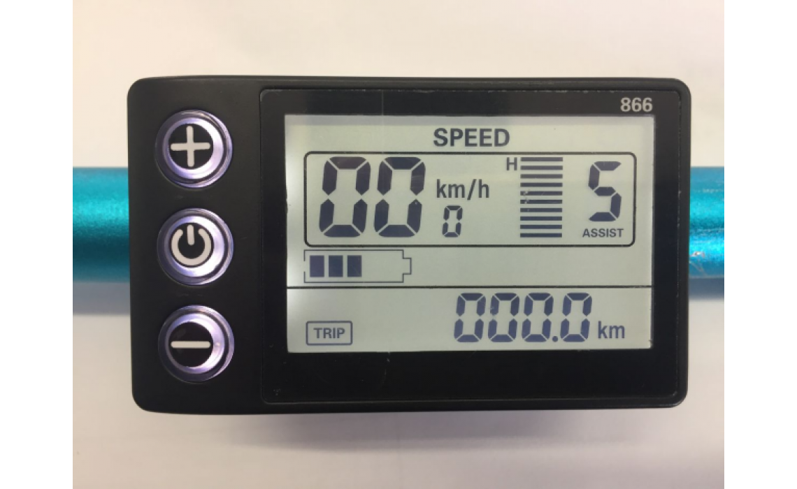
Throttle plus PAS shorted = error 10

criispyhere

Finding my (electric) wheels
Apr 1, 2023
8
0
Hi guys, due to poor english used in instruction delivered with controller I've been fighting a lot to get to work the gas throttle. I get it to work after few hours but then the pas stopped to work. I knew that it was working before at the same plug as throttle so I had an genius idea to connect it together. First the throttle shifter with the sensor and then everything together to a throttle plug from controller. Since this time the motor gives an error 10 and brake failure icon appears. We are talking about XLD Controller and s866 display. I tried another controller as well and it's not working.
 

Attachments

AGS

Esteemed Pedelecer
Feb 12, 2023
608
190
PAS inputs 5 volt pulses into the controller created by a set of magnets rotating around a magnetic sensor when you pedal. The faster you pedal the higher the frequency of the pulses.

Throttle inputs 0 to 3.6 volts dc, created by twisting the throttle. The more you twist the higher the dc voltage.

You should only connect pas to pas and throttle to throttle. You should not connect pas to throttle, or throttle to pas, and definitely not pas and throttle to throttle, or pas and throttle to pas.

It looks like you have several problems with your wiring if the brake failure warning has also come on. So do your testing without the brake sensors connected. And sort that problem out when you have got the motor working properly.

And when you are testing, make sure you select pas 1 on the display. You won’t get anywhere if you select pas 0 because neither throttle nor pas will be activated on pas 0.

Search for “brainpower motor controller wiring diagram” there are plenty of images and videos on line showing how to connect it up properly and also how to set up the “learn” function.
 
Last edited:

Nealh

Esteemed Pedelecer
Aug 7, 2014
20,981
8,565
61
West Sx RH
As indicated the wiring togethef of PAS & throttle has produced the error 10 which is a signal receiving error , the controller senses the signal is wrong as it is different for both peripherals.
Quite often with these cheap kits faults seem to be not uncommon with the electrics both the display and controller suffer from QC faults so one has to look here for the answer.
Use a meter and test the peripherals seperately as they are supposed to be wired up and see if any show up a fault.

Probe the throttle Gnd to 5v , then Gnd to sig and finally with Gnd to sig with the throttle open. Tell us the three voltages you see on the meter for each test.

Like wise do the same for PAS except on the third option one will have to rotate the pedals /cranks for the on /off voltage test as the magnets pass the sensor.

From the posted results you tell us , a possible fault may be staring us in the face.

The cheap controller kits although tempting aren't worth the hassle and one is better off paying the extra for a nicer regarded controller/display combo.
 

saneagle

Esteemed Pedelecer
Oct 10, 2010
7,005
3,241
Telford
Hi guys, due to poor english used in instruction delivered with controller I've been fighting a lot to get to work the gas throttle. I get it to work after few hours but then the pas stopped to work. I knew that it was working before at the same plug as throttle so I had an genius idea to connect it together. First the throttle shifter with the sensor and then everything together to a throttle plug from controller. Since this time the motor gives an error 10 and brake failure icon appears. We are talking about XLD Controller and s866 display. I tried another controller as well and it's not working.
If you want both throttle and PAS to work, you must change settings in the LCD.
P09 =0
P10=2

You got error 10 when you connected together your throttle and PAS, it's because you effectively joined the 5v power to ground, so no 5v to drive the cpu in the controller, nor anything else. The LCD has its own 5v, so it's not affected by that, but everything else is. You must not leave it like that for long because the 5v regulator will over-heat and blow. If you get error 10 after you connect everything back correctly, you need to replace the 5v regulator or buy a new controller.
 

criispyhere

Finding my (electric) wheels
Apr 1, 2023
8
0
If you want both throttle and PAS to work, you must change settings in the LCD.
P09 =0
P10=2

You got error 10 when you connected together your throttle and PAS, it's because you effectively joined the 5v power to ground, so no 5v to drive the cpu in the controller, nor anything else. The LCD has its own 5v, so it's not affected by that, but everything else is. You must not leave it like that for long because the 5v regulator will over-heat and blow. If you get error 10 after you connect everything back correctly, you need to replace the 5v regulator or buy a new controller.
The 5v regulator is in the engine also? Because I check already with stock controller together with stock display and it's not working. That means i bricked engine somehow but cannot check what's inside. Need to get extended key, somebody put the pegs before the nut goes
 

AGS

Esteemed Pedelecer
Feb 12, 2023
608
190
The 5 volt regulator is inside the controller. It is unlikely you have damaged the motor by connecting the pas and throttle wires together.

If you have a multimeter you can check the voltages on the pas and throttle connectors as Nealth suggested.

You do have to be careful about cross connecting the wiring because you can damage the controller quite easily.
 
  • Like
Reactions: criispyhere

saneagle

Esteemed Pedelecer
Oct 10, 2010
7,005
3,241
Telford
The 5v regulator is in the engine also? Because I check already with stock controller together with stock display and it's not working. That means i bricked engine somehow but cannot check what's inside. Need to get extended key, somebody put the pegs before the nut goes
There is nothing in the motor you can brick by connecting a throttle or PAS in the wrong way. There are hall sensors in the motor that run from 5v and are connected by the thin wires in the motor cable. You can kill them if you somehow connect battery voltage to them, but that's almost impossible to do.

If your bike falls on the ground, it's possible to damage the motor cable where it comes out of the axle. In that case, the motor wires might touch the hall sensor wires. That can blow both the hall sensors and controller.

When an ebike doesn't work and you don't know why, the best way to solve it is by using a meter to measure voltages in logical steps that will always show you where the fault is.
 
  • Like
Reactions: criispyhere

criispyhere

Finding my (electric) wheels
Apr 1, 2023
8
0
Multimeter is on the way. I ordered from ali few days ago so I'll wait untill it will arrive here. By the way is it normal that display shows 41 volts used if my battery is 36v? I don't think so?

Now I realised that I connect the self learning wire that time when I connect PAS + throttle. Maybe this is the problem also?
 

Attachments

Last edited:

AGS

Esteemed Pedelecer
Feb 12, 2023
608
190
Here is an example of a battery voltage chart. A 36 volt battery will be at 42 volts when it is fully charged, so it’s nothing to worry about.

Post a photo of your controller showing the plugs and sockets that you have connected and someone may be able to advise you of what testing you need to do while you are waiting for your multimeter to arrive.

9C897618-3C73-40B2-9B91-E20AFA8BF8FA.png
 
Last edited:
  • Like
Reactions: criispyhere

criispyhere

Finding my (electric) wheels
Apr 1, 2023
8
0
Here is an example of a battery voltage chart. A 36 volt battery will be at 42 volts when it is fully charged, so it’s nothing to worry about.

Post a photo of your controller showing the plugs and sockets that you have connected and someone may be able to advise you of what testing you need to do while you are waiting for your multimeter to arrive.

View attachment 50969
No needed picture, I understand for now every connection which I make and as @saneagle and you @AGS say it's gonna be the 5v regulator broken.

I noticed that they are also inside of motor.
Probably I'm gonna do same operation as the guy here on YouTube if I'll get all the parts and tools needed.
 

AGS

Esteemed Pedelecer
Feb 12, 2023
608
190
The 5 volt regulator is inside the controller, not in the motor. And you don’t know if it’s damaged yet until you get your multimeter so you can check voltages on the pins.

The circuit board that you see in the motor is for the hall sensors. They get their 5 volt supply from the controller.

You don’t need to take your motor apart at this stage.

If you post some photos of the controller and your connections then someone may be able to advise you of what you have connected correctly and incorrectly so far. And also how to use the multimeter to check voltages. It looks like you have connected the display properly, so that’s a good start.

Also you will need to check the settings on the display to ensure pas and throttle are activated as previously mentioned by saneagle. Use the manual that he has linked to in his reply to set up all of the display parameters correctly. If you are unsure about any of the settings then post here and someone will help.
 
Last edited:

criispyhere

Finding my (electric) wheels
Apr 1, 2023
8
0
The 5 volt regulator is inside the controller, not in the motor. And you don’t know if it’s damaged yet until you get your multimeter so you can check voltages on the pins.

The circuit board that you see in the motor is for the hall sensors. They get their 5 volt supply from the controller.

You don’t need to take your motor apart at this stage.

If you post some photos of the controller and your connections then someone may be able to advise you of what you have connected correctly and incorrectly so far. And also how to use the multimeter to check voltages. It looks like you have connected the display properly, so that’s a good start.

Also you will need to check the settings on the display to ensure pas and throttle are activated as previously mentioned by saneagle. Use the manual that he has linked to in his reply to set up all of the display parameters correctly. If you are unsure about any of the settings then post here and someone will help.
As I said before. I have stock controller + display and another pair which i bought from Internet. Both of them are showing errors and before were working totally fine. The only same part which I use is battery and motor. Battery has own BMS so I guess it's ok but motor reports error 10 and the guy on the video has the same error. After he change all three regulators the problem is gone. That's what I'm going to check first once I get multimeter.

Nothing is connected to be honest. Only hall sensor and battery. All the colors appears to be the same so no philosophy here. It was working before, connected this way. And about the settings I was playing there for a while. It's problem on hardware level.
 
Last edited:

flecc

Member
Oct 25, 2006
53,260
30,648
say it's gonna be the 5v regulator broken.

I noticed that they are also inside of motor.
Probably I'm gonna do same operation as the guy here on YouTube if I'll get all the parts and tools needed.
He is not changing three regulators, he is changing the three Hall sensors in the motor.

As you've been told, the 5 volt regulator is in the controller, NOT in the motor. However you may have blown the Hall sensors if you've directly put the battery 42 volts through them, but that is unlikely.
.
 
Last edited:

criispyhere

Finding my (electric) wheels
Apr 1, 2023
8
0
He is not changing three regulators, he is changing the three Hall sensors in the motor.

As you've been told, the 5 volt regulator is in the controller, NOT in the motor. However you may have blown the Hall sensors if you've directly put the battery 42 volts through them, but that is unlikely.
.
Oh ok, looks similar. I'm gonna check what I need to order once I get in there. By the part number I will figure out. Thanks guys for make the things brighter for me!
 

saneagle

Esteemed Pedelecer
Oct 10, 2010
7,005
3,241
Telford
You don't open the motor to test it. Everything can be done through the cable or at the controller end.

You test the controller first to see if the 5v regulator is blown. Connect only the battery and LCD, nothing else. Switch on the LCD and measure the voltage between any of the thin red and black wires on the PAS, throttle or motor connector. It should be around 5v if the regulator is working. In case the LCD is faulty when you don't get 5v, disconnect it and join the red and blue wires with a paper clip in the connector and test the 5v again.

Did you check your motor cable for damage?
 
Last edited:

Advertisers