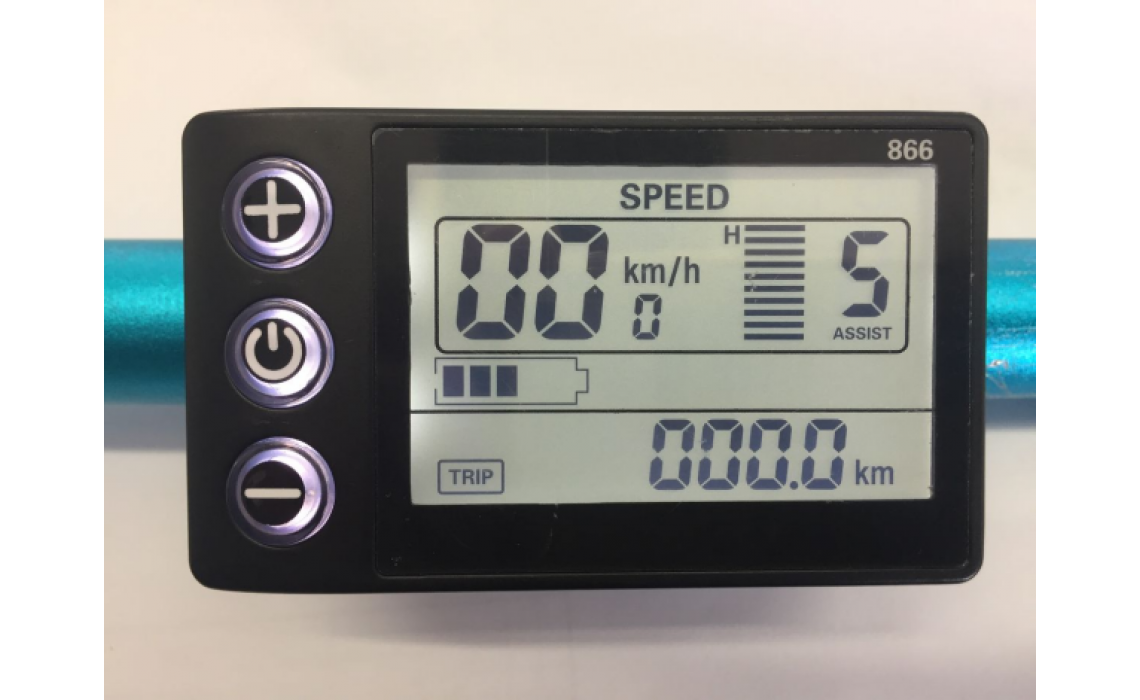
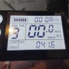
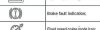
Hi guys, due to poor english used in instruction delivered with controller I've been fighting a lot to get to work the gas throttle. I get it to work after few hours but then the pas stopped to work. I knew that it was working before at the same plug as throttle so I had an genius idea to connect it together. First the throttle shifter with the sensor and then everything together to a throttle plug from controller. Since this time the motor gives an error 10 and brake failure icon appears. We are talking about XLD Controller and s866 display. I tried another controller as well and it's not working.
Attachments
-
 377.7 KB Views: 10
 -
 78.8 KB Views: 8