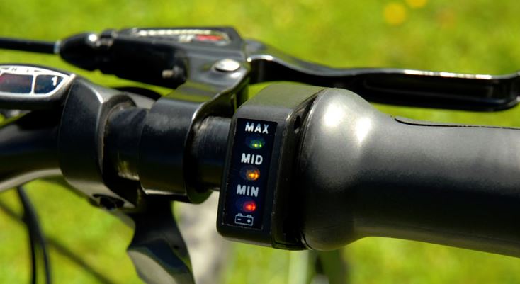
Thanks, I uploaded a file (coveconn.jpg), new to forum so not sure where to view. There are 3 connectors, red one just for charging. The motor connector has 8 pins: 3 phase, 3 hall sensor and 5v, 0v for hall power. The green throttle connector uses four pins: 5v, 0v, throttle input, and 36v ( presumably to show charged state on throttle leds). I am putting 5v across throttle input and 0v pin to simulate full throttle. On the motor connector I put 5v , 0v, 0v combination on the hall sensor pins to simulate a rotation position ( ground attached to the 0v pin of the hall sensor power ground pin so grounds are linked). I figured this represents a stationary state of a wheel so on twist and go I should see something on one of the phase wires trying to turn the motor?
I appreciate I really need a throttle and a brushless motor in a wheel, situation is I inherited controller with good battery and trying to decide if its worth buying the rest.


