hi all hope everybodys safe and well
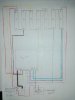
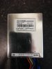
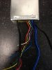
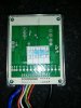
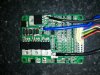
im looking for some help in wiring an old 7s LT-POWER pcm to a 7s5p battery
i have searched the internet but cannot find any details on this hope somone can help
all the best
im looking for some help in wiring an old 7s LT-POWER pcm to a 7s5p battery
i have searched the internet but cannot find any details on this hope somone can help
all the best
Attachments
-
 3.2 MB Views: 11
 -
 3.2 MB Views: 12
 -
 3.2 MB Views: 12
 -
 5.4 MB Views: 11