PAS or Controller problem

Cyryl

Finding my (electric) wheels
Aug 2, 2024
9
0
Hello everyone!

A few days ago my E-bike stopped pedal assisting. The model is Wayscral City 415, it’s a cheap Chinese E-bike, but it’s just 1 year old.

What have I already tried:
1. Tested the voltage of my battery - it’s 40v. Should be 36v, so I guess it okay.
2. Tested the continuity of the motor - all three wires have it.
3. The PAS sensor was completely fried, so I tried replacing it. The wires didn’t match, so I tried reconnecting them in all possible combinations and steering the pedals. The motor remained inactive.

And that’s when I noticed a few very strange things. The most important one being this:59161
59162
The voltage is only 0.9v on both signal and power cables of the PAS sensor! It’s not only lower than the 5v I see in every related post, but it also doesn’t change when I start spinning the magnet near the sensor.
At this point I am completely lost. Is my controller broken? Is my sensor connected in a wrong way?
If you have any suggestions, please tell me, I’ll be glad to test them.
 

Cisco-man

Esteemed Pedelecer
Sep 27, 2023
297
72
One wire of the three is constant 0v, one is constant 5v, the last is signal. If you can’t find 0v and 5v wires then something is fried I guess. Don’t rely on colour coding though.
 

saneagle

Esteemed Pedelecer
Oct 10, 2010
7,007
3,241
Telford
A little knowledge can be a dangerous thing.

I can't understand what you've done, but what you show is wrong in both photos. First, disconnect the pedal sensor, then, on the controller side, check which is the ground by measuring the continuity to the battery ground. Next, check the voltage on the red wire, which should be 5v. If it's still 0.9v, then you've got a short on the 5v somewhere or you've blown the 5v regulator, probably when you shorted the 5v to ground by misconnection. 5v regulators cost pence from Ebay and are fairly easy to replace.

Before replacing the regulator, disconnect everything from the controller except the battery and LCD (if you have one). Switch it on and check the 5v. If it comes back, you have a short, if it doesn't, the regulator is blown.
 

Cyryl

Finding my (electric) wheels
Aug 2, 2024
9
0
First, disconnect the pedal sensor, then, on the controller side, check which is the ground by measuring the continuity to the battery ground.

Before replacing the regulator, disconnect everything from the controller except the battery and LCD (if you have one). Switch it on and check the 5v. If it comes back, you have a short, if it doesn't, the regulator is blown.
Thanks a lot! Most likely I really did something stupid. Following your instructions I found the ground, it’s the black cable.
But after disconnecting everything, something interesting happened. Now the red wire reads as 1.08v and the yellow one as 0.95v. I guess, it means my regulator is blown, right?
 

Nealh

Esteemed Pedelecer
Aug 7, 2014
20,982
8,565
61
West Sx RH
Issues are always down to the user not knowing what they are doing, we see it often . Wires are willy nilly connected without having a clue or checking/testing wiring sequences first.
It is only when something gets smoked that the logic kicks in to aske for help but by then the damage is usually done.
With any ebike wiring one must check which is gnd & 5v from the controller.

When you cut the cable and rejoined them , why on earth did you think it would be ok to change the wire colour sequence.
One has to think logically , one would do such a silly thing on your home electrics or would you ?
 

Cyryl

Finding my (electric) wheels
Aug 2, 2024
9
0
When you cut the cable and rejoined them , why on earth did you think it would be ok to change the wire colour sequence.
One has to think logically , one would do such a silly thing on your home electrics or would you ?
Sadly, when I tried plugging in the sensor as it was it just refused to work. Then I found threads of people with the same problem, and this message: “Alternatively, you can try the wires in all six combinations until you get the one that works, starting with red to red, black to yellow and blue to white” (https://www.pedelecs.co.uk/forum/threads/pas-sensor-wiring.36133/post-529267)
It encouraged me to try connecting them in different order. Now I understand how big of a mistake it was.
 

Cyryl

Finding my (electric) wheels
Aug 2, 2024
9
0
With any ebike wiring one must check which is gnd & 5v from the controller.
Looks like I won’t be able to replace the regulator and will have to buy a new controller. And when I’ll get it, what should I try next? I’ll be able to tell which controller wires correspond to 5v, ground and signal. But how can I find out the correct way to connect the sensor wires without frying my controller again?
 
Last edited:

Nealh

Esteemed Pedelecer
Aug 7, 2014
20,982
8,565
61
West Sx RH
Asking first is better then guessing .
Straight away we would have told you PAS = yellow /gnd, Red /5v & blue signal. Connecting to the controller would have been been simple once one confirmed the controller PAS output voltage was ok.
 

Nealh

Esteemed Pedelecer
Aug 7, 2014
20,982
8,565
61
West Sx RH
Typically with nearly most china wiring one can be certain that Black is gnd if not present then Yellow .
Red is 5v or if not present Brown.
After that signal is the obvious third colour.

Blue is used for volatge but that is usually additional voltage wiirng on displays.

It is only with obscure colours that one will need to ask for assistance .

It is easy testing which is Gnd/5v form the controller , one can't really go wrong.
Most peripherals will have a wire sequence indicated at the point of sale /web page, other wise one should be able to cipher the colours .

The issues can arise when any of the above aren't used.
Your PAS wiring is simple logi bearing in mind the above.
 

saneagle

Esteemed Pedelecer
Oct 10, 2010
7,007
3,241
Telford
Sadly, when I tried plugging in the sensor as it was it just refused to work. Then I found threads of people with the same problem, and this message: “Alternatively, you can try the wires in all six combinations until you get the one that works, starting with red to red, black to yellow and blue to white” (https://www.pedelecs.co.uk/forum/threads/pas-sensor-wiring.36133/post-529267)
It encouraged me to try connecting them in different order. Now I understand how big of a mistake it was.
It's not a problem to ground the 5v regulator for a few seconds for testing, but if you leave it like that for several minutes, it can overheat and blow. Did you disconnect everything, including the motor cable? If so, you either need a new controller or replace the regulator, which involves unsoldering three legs and soldering in the replacement. Anybody can do it.
 

Cyryl

Finding my (electric) wheels
Aug 2, 2024
9
0
It's not a problem to ground the 5v regulator for a few seconds for testing, but if you leave it like that for several minutes, it can overheat and blow. Did you disconnect everything, including the motor cable? If so, you either need a new controller or replace the regulator, which involves unsoldering three legs and soldering in the replacement. Anybody can do it.
Yes, I disconnected every cable except for the battery and the panel on my handlebars. Actually, I want to learn the basics of soldering, but I don’t think this situation is appropriate. Anyways, I’ve ordered the controller, it should arrive at Monday and then we’ll see.
 

Cyryl

Finding my (electric) wheels
Aug 2, 2024
9
0
It's not a problem to ground the 5v regulator for a few seconds for testing, but if you leave it like that for several minutes, it can overheat and blow. Did you disconnect everything, including the motor cable? If so, you either need a new controller or replace the regulator, which involves unsoldering three legs and soldering in the replacement. Anybody can do it.
By the way. When you say “Blow”, do you mean it literally? Because I have 7 regulators on my board and none of them look damaged. Also, in case if I’ll decide to try repairing this board, how can I find the regulator I need to replace?59167
 

Cisco-man

Esteemed Pedelecer
Sep 27, 2023
297
72
Read the numbers on the items. It’s likely to be the single one at the top of your board in the photo, but you’re looking for a number stamped on it something like 7805.
 

saneagle

Esteemed Pedelecer
Oct 10, 2010
7,007
3,241
Telford
By the way. When you say “Blow”, do you mean it literally? Because I have 7 regulators on my board and none of them look damaged. Also, in case if I’ll decide to try repairing this board, how can I find the regulator I need to replace?View attachment 59167
You have two regulators. The 36v comes in top left, goes through the big upright resistor to the 12v regulator, which is the black thing to the left or the resistor. The 12v regulator supplies 12v for the MOSFET switching and also the 5v regulator, so the 5v regulator is somewhere near the 12v one. I can't see it in your photo, it might be hidden by the other stuff or on the backside as a surface mount component, which would be more difficult to repair. The 5v regulator supplies the power for the CPU and all the sensors.

This is a more typical arrangement, where the 5v regulator is standing up to the right of the 22v one:


Cyryl

Finding my (electric) wheels
Aug 2, 2024
9
0
You have two regulators. The 36v comes in top left, goes through the big upright resistor to the 12v regulator, which is the black thing to the left or the resistor. The 12v regulator supplies 12v for the MOSFET switching and also the 5v regulator, so the 5v regulator is somewhere near the 12v one. I can't see it in your photo, it might be hidden by the other stuff or on the backside as a surface mount component, which would be more difficult to repair. The 5v regulator supplies the power for the CPU and all the sensors.

This is a more typical arrangement, where the 5v regulator is standing up to the right of the 22v one:

Huge thanks!
 

Nealh

Esteemed Pedelecer
Aug 7, 2014
20,982
8,565
61
West Sx RH
The 5v regulator is clear to see , top right of board next to the beige resistor.
 

saneagle

Esteemed Pedelecer
Oct 10, 2010
7,007
3,241
Telford
The 5v regulator is clear to see , top right of board next to the beige resistor.
Where's the 12v regulator then? There's something unconventional about that board because there's a second big resistor lying down. I've not see that before.
 

Nealh

Esteemed Pedelecer
Aug 7, 2014
20,982
8,565
61
West Sx RH
We will know for sure what it is , if it has a code on it.
 

Cyryl

Finding my (electric) wheels
Aug 2, 2024
9
0
Hello again. So, I’ve received my new controller but it didn’t solve the problem.
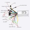
Right now the controller is connected to the battery. The motor is connected to controller. Green wire to green. Yellow to yellow. Blue to purple-ish blue59233
PAS sensor is also connected. For some reason PAS on this controller is called 1:1 accelerator
59236
but I found the ground (it’s the yellow cable) checked the voltages and the blue cable had 5.05 while the red one had 4.7. I figured out that the blue should be the power and the red is the signal. So this is howI connected the cables:
59237
The new screen is also connected to the controller. It works and when I connected so called “intelligent identification” cables and chose the speed 1, the wheel started spinning!
Yet it still doesn’t respond to my sensor.
What have I done wrong now and what should I test?
 

Cyryl

Finding my (electric) wheels
Aug 2, 2024
9
0
Never mind, I just needed to swap the signal and power wires on the side of the sensor. Now it works!

Huge thanks to everyone!