I have a 1000w 48v brushless rear hub motor with the supplied 48v 1000w controller.
I also already have a 36v 12ah lithium-ion battery pack and charger which I`d like to use with it for now (while I save more money up !)
Reading the forum, I understand that the motor should work ok with 36volts, giving out a max power of about 750w, and would actually be under less stress than it`s specified 48v construction.
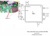
I do need to alter the low voltage protection circuit in the controller though, as it won`t run because it thinks the voltage from the 36v is too run down from the expected 48v.
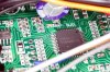
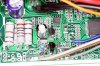
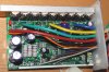
I`ve opened the controller and it all seems nice an clear in there with accessible components. I just need to know which resistors to change !!
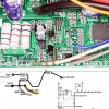
Is there anywhere where I might be able to download a circuit diagram ? It`s marked as " Brushless DC motor controller DM4825Li". I could photograph the board, and it is nice and clearly marked with abbreviations etc.
I also already have a 36v 12ah lithium-ion battery pack and charger which I`d like to use with it for now (while I save more money up !)
Reading the forum, I understand that the motor should work ok with 36volts, giving out a max power of about 750w, and would actually be under less stress than it`s specified 48v construction.
I do need to alter the low voltage protection circuit in the controller though, as it won`t run because it thinks the voltage from the 36v is too run down from the expected 48v.
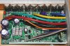
I`ve opened the controller and it all seems nice an clear in there with accessible components. I just need to know which resistors to change !!
Is there anywhere where I might be able to download a circuit diagram ? It`s marked as " Brushless DC motor controller DM4825Li". I could photograph the board, and it is nice and clearly marked with abbreviations etc.

")