Home-made power strip for multiple tapping

103Alex1

Esteemed Pedelecer
Sep 29, 2012
2,228
67
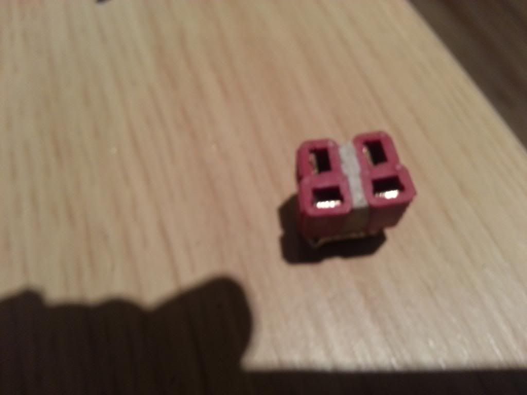
Came across this tonight. They say if you search long enough & all that .... Power strip made out of Deans connectors. Put together by some RC guys for their Lipos, but equally suitable for running multiple circuits off your bike battery I'd have thought :-

RC Groups - View Single Post - WHATS BETTER? Deans type, XT60, or EC3 connectors?

No screw-down terminals to break or shake loose. Think I might have a go at making one of these, which could be a 6-way or even an 8-way - just add another connector to the strip for each circuit you want to have available to run off your battery. Total cost about £4.50.

I'm guessing it should be attached to the controller side of my FET on/off switch, which would make the FET switch turn the entire power strip on/off, which is the basic idea of a master power supply distribution solution that I've had in mind all along.

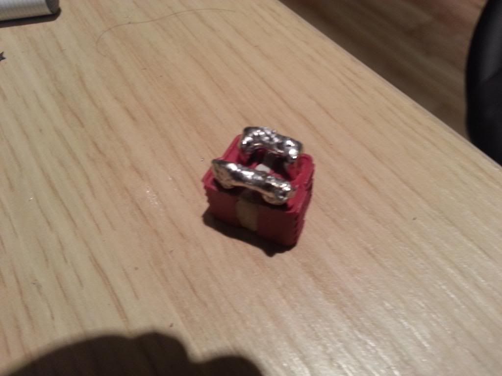
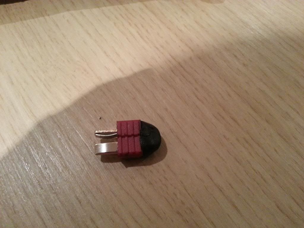
Rather than make a messy job of it tapping wires or making t-joins all over the place each of my 6-8 circuits can just plug into any one of the Deans females on the power strip. If I want to disconnect an accessory I just unplug it from the Deans power strip. Job done.

Any idea what would be the best thing to coat the power strip along the back of the Deans females with to ensure no shorting and to protect the device ?
 

Old_Dave

Esteemed Pedelecer
Sep 15, 2012
1,211
2
Dumfries & Galloway
Any idea what would be the best thing to coat the power strip along the back of the Deans females with to ensure no shorting and to protect the device ?
If its really needed... then most of the squirty Silicones will do the trick, and I prefer XT60 cos they are more water resistant by design.

Bit ott for this voltage / current purpose so I could be persuaded to consider something lesser... maybe :p
 
Last edited:

103Alex1

Esteemed Pedelecer
Sep 29, 2012
2,228
67
Guess you can bond different connectors together to form a strip so long as the contacts are properly seated within the strip solder and they're decently glued together at the sides. I already have some spare Deans from the original controller setup but rest of power strip can be made up of anything similar sized.

Never used XT60s .. I read somewhere once that it was possible to mate them the wrong way round if you were not thinking - and passed them over more on account of that than anything else tbh. Never having handled them I don't know quite how much you'd have to not be thinking to do that tho' :) There's not much in it (if anything) cost-wise between a 'decent copy' XT60 & a 'decent copy' Deans !

Away from the power strip connection will go to fuse / switch anyhow so the other end won't be deans will be something else. It dawned yesterday that it's basically a wiring loom I've been trying to plan without really realizing and now I think about it like that it's much easier to get my grey cells organized to make it.

When I get back and start working on the bike again, and can actually see everything laid out, it'll all become clear what best to use I'm pretty sure.
 
D

Deleted member 4366

Guest
You should only use connectors where you need to disconnect, otherwise solder the wires into a loom.
 

103Alex1

Esteemed Pedelecer
Sep 29, 2012
2,228
67
There'll be a mix of them and it doesn't seem "joined up" to me for some reason .. I've never seen a car or motorbike wiring loom disassembled to understand how they build them so maybe that's half the trouble.

If I start soldering 4-5 wires together at one end then the likelihood is the join won't be strong, surely ... just one big bundle that'll be prone to breaking apart :confused: There is only one main black and one red supply wire off which everything else will fan out after the FET switch (including the controller). A series of connector points to use to plug in each circuit just seems a far neater way of doing things - and allows the whole thing to be chopped and changed at will just by unplugging a circuit and swapping it for something else.

I kind of like neat, tidy, flexible, logical, modular if you know what I mean. Like fuse boxes and the like. The motor is only 1/5 or 1/6 of the picture - albeit the one which will take the lion's share of the power. Soldering a big jumble of wires together doesn't sit well with my sensibilities lol. Is there going to be huge power losses through using a power strip ?
 

Old_Dave

Esteemed Pedelecer
Sep 15, 2012
1,211
2
Dumfries & Galloway
Connectors induce.losses.... However for our uses the effect of losses are 0, XT60's can not be plugged in the wrong way unless you use a knife and a hammer, lol


Sent from my iPhone using Tapatalk
 

Alan Quay

Esteemed Pedelecer
Dec 4, 2012
2,351
1,076
Devon
Why not buy a small, automotive fuse box, feed it with one (suitably sized) cable and take each circuit from there?
 

103Alex1

Esteemed Pedelecer
Sep 29, 2012
2,228
67
Why not buy a small, automotive fuse box, feed it with one (suitably sized) cable and take each circuit from there?
How does that rig up, Mike ?

Need to split black and red wires several ways and fuse boxes only looked like they were designed for routing multiple positive feeds across the connector pins each side of the fuse slots.

8 Way Circuit Standard / Mini Blade Fuse Box / Holder Universal With Cover | eBay

I actually looked at this fuse box and thought about routing all my positive feed circuits through it at one stage rather than having a bunch of inline fuses of appropriate amps rating on each separate feed. Since the fuse box is mountable and has a screw-down lid, seems a neat way of organizing your circuit fuses with a numbered system and very easy to check and change as needed.

However I don't quite follow how that helps with the upstream issue of branching a single feed into several others before you take each branch across a fuse. The purpose of the power strip was a neat space-saving way of having what is in effect like a minature Busbar with common 0V feed point too (or whatever the technical terminology is for it !) all in one little block. Everything you want to feed off the battery has its own black and red wires plugging in to a Deans female slot so no wire tapping is needed with a power strip.
 
Last edited:

hech

Esteemed Pedelecer
Oct 29, 2011
352
27
argyll
Aha Alex my old adversary, if you thought I dont read your seedy posts anymore on account of their excrutiating boredom you were so very wrong my friend. What you do with your time in downtown power-strip joints and bus-bars was of no interest to me but then this idle chat about those lovely Deans women and your disgraceful boast of "plugging" them is jus beyond the pale. You'll be saying you were out "haibiking" them next I suppose, I tell you now Ive had just about or more than enuff!
 

amigafan2003

Esteemed Pedelecer
Jul 12, 2011
1,389
139
Aha Alex my old adversary, if you thought I dont read your seedy posts anymore on account of their excrutiating boredom you were so very wrong my friend. What you do with your time in downtown power-strip joints and bus-bars was of no interest to me but then this idle chat about those lovely Deans women and your disgraceful boast of "plugging" them is jus beyond the pale. You'll be saying you were out "haibiking" them next I suppose, I tell you now Ive had just about or more than enuff!
You're a very strange man!
 

Alan Quay

Esteemed Pedelecer
Dec 4, 2012
2,351
1,076
Devon
How does that rig up, Mike ?
You need to find a small fuse box with a single 'busbar' feed. Had a quick look on Ebay, and there are some that will do the job, however they all have fuse blown indicator LED's, and are rated up to 32v (presumably for the LED). I would be inclined to remove the LED, then feed with a single wire.

Alternatively, this comes with a ready made cable. I guess you could solder & heat shrink the wires on if you don't have crimpers.

6 Way Heavy Duty Fuse Box Kit with pre-spliced Main Cable, Fuses - split charge | eBay

Similarly, with the 0v's:

DURITE 0-005-52 2 x 4 WAY TERMINAL CONNECTOR BLOCK 25A | eBay
 

hech

Esteemed Pedelecer
Oct 29, 2011
352
27
argyll
.................................................................................................................................................................


:mad:
 

flecc

Member
Oct 25, 2006
53,361
30,710
.................................................................................................................................................................


:mad:
Shouldn't Morse Code have dashes as well? :confused:
 

103Alex1

Esteemed Pedelecer
Sep 29, 2012
2,228
67
Alternatively, this comes with a ready made cable. I guess you could solder & heat shrink the wires on if you don't have crimpers.

6 Way Heavy Duty Fuse Box Kit with pre-spliced Main Cable, Fuses - split charge | eBay
In principle, it looks just the job. The pre-spliced wire is GREAT - nice 'n' easy and pretty sure I can work with a 6-way. Shame you can't get those pre-spliced main wires separately - would be really useful in a number of things - but it's a really decent price for that package :D.

What crimpers do you use for the female connectors ? Wretched things were on a battery charger I was trying to repair and managed to drive an awl clean through the flesh of my thumb tip trying to get the crimp connector out of the insulated housing on the replacement a couple of days ago. Missed the bone thankfully but the awl exited over a centimetre away from where it entered my thumb - a definite "f*** these blasted things" moment lol ! I

To add insult to injury Halfords had sold me the wrong size for the wire being crimped and it just slid right out without gripping securely. Looked like this but in blue ... I think they're called Lucar connectors and look very similar to the ones compatible with those fuse box terminals :

6.4mm Red Female Spade Terminals (Insulated) x 100 | eBay

An attempt to solder it on also failed - the Toolzone 60/40 solder I was using with a Maplins 50W solder station (only stuff I could get down here at short notice) wouldn't adhere to the supposedly tin-plated crimp terminal (or tin the heated wires come to think of it :rolleyes:). So something didn't want to play ball. Seems like they're determined to have you spending over £20 on a wretched crimping tool, by hook or by crook :) !!!!!!!!

Do you just route the main black to one of those pins then and run a 0v from each circuit back to another pin on the same block ? Is that what people refer to as a "common ground" point ?
 
Last edited:

Alan Quay

Esteemed Pedelecer
Dec 4, 2012
2,351
1,076
Devon
.....Shame you can't get those pre-spliced main wires separately - would be really useful in a number of things - but it's a really decent price for that package :D.
Very easy to make with a bit of cable, a soldering iron, and some heat shrink sleeve. 5 minutes work.

What crimpers do you use for the female connectors ? Wretched things were on a battery charger I was trying to repair and managed to drive an awl clean through the flesh of my thumb tip trying to get the crimp connector out of the insulated housing on the replacement a couple of days ago. Missed the bone thankfully but the awl exited over a centimetre away from where it entered my - a definite "f*** these blasted things" moment lol ! I
Ok, I think I'm starting to understand why you hate them. To be very clear - You DO NOT need to remove the plastic outer with and awl. you insert the cable through the plastic, into the steel part, and crimp the entire thing. Takes about 5 seconds, and requires no soldering.

To add insult to injury Halfords had sold me the wrong size for the wire being crimped and it just slid right out without gripping securely. Looked like this but in blue ... I think they're called Lucar connectors and look very similar to the ones compatible with those fuse box terminals :
Important to have the correct size crimp for the cable. The colours relate to the size of the cable. Red, Blue and yellow. You will mostly need red. Sometimes blue, especially if you want to insert 2-3 cables in one crimp. Lucar appears to be another name for spade terminals. You will need females.


An attempt to solder it on also failed - the Toolzone 60/40 solder I was using with a Maplins 50W solder station (only stuff I could get down here at short notice) wouldn't adhere to the supposedly tin-plated crimp terminal (or tin the heated wires come to think of it :rolleyes:). So something didn't want to play ball. Seems like they're determined to have you spending over £20 on a wretched crimping tool, by hook or by crook :) !!!!!!!!

Hmmmmm, not sure about this.


Do you just route the main black to one of those pins then and run a 0v from each circuit back to another pin on the same block ? Is that what people refer to as a "common ground" point ?
That's the idea, and yes, often called a common. In this case, not a ground though, unless you have conductive tyres.
 

Alan Quay

Esteemed Pedelecer
Dec 4, 2012
2,351
1,076
Devon
Seems like they're determined to have you spending over £20 on a wretched crimping tool, by hook or by crook :)
9" Crimping Tool Ratchet Type, Plus 100 Mixed Crimping Terminals | eBay

Cant comment on quality, but it looks alright from the picture. Comes with a few female spades (blue) so I would also order some reds.

A good article on crimping:
http://www.instructables.com/id/How-to-Make-A-Quality-Crimped-Joint/step4/Making-the-Crimp/

(but dont worry about a micrometer/vernier for measuring cores - use the crimp that fits tightest)

Honestly, once you get the hang of it it really will save you loads of effort. And once you work out that you can crimp more than one wire into a terminal........
 
Last edited:

103Alex1

Esteemed Pedelecer
Sep 29, 2012
2,228
67
Thanks a lot Mike - that's all very interesting and very helpful. Will be back working on the bike again Thursday hopefully so this answers many of my remaining questions and head-scratching. Can pretty much picture how it's all going to work in my head now and can get on with assembling my box with a far better idea of everything that's going to need fitting in it.

I'm going to give the fuse box a go and get one of those earth return Durite blocks too. Reckon I can fit some softwood inside the box to give a surface to screw the fuse box and Bus to in a way they can be easily accessed and maintained / fuses replaced as needed.

It's going to be a tight fit in there with the battery, controller, fuses, switches and DC-DC converters, but having an organized arrangement like this should help make things easier to manage space-wise .. and I can play about with what goes where with all the bits to hand, which is the only way it's going to work.

Just my Cycle Analyst to arrive now and I should be pretty much all set to finish the job. Rang them on Friday and they still hadn't dispatched my paid order from Tuesday. Poor show that :(. They promised to send out Friday but never even got an invoice or confirmation from Grin, just a note from PayPal saying my money had gone. Oh the joys of importing !
 

103Alex1

Esteemed Pedelecer
Sep 29, 2012
2,228
67
Right, well I decided to use the idea to split my supply 2-ways from the other side of the FET isolator switch. It means I can plug in my Controller into one and all my other circuits into the other. Handy way of splitting the supply and no need to tap my main wire.

This is how I made it :

First, epoxy 2 Deans female connectors together with fast setting repair putty that sets like billy-o :


Next, make solder bridges between the 2 +ve pins and the 2 -ve pins on the back :


Third, make a blanking plug that can be popped in if I'm not using both outlets :


The pins are covered in Sugru, a fantastic self-setting insulating rubber as recommended by KirstinS. It's amazing stuff and I'm totally sold on it.