Hi! Help Needed

Ryds

Finding my (electric) wheels
Jun 14, 2017
9
0
46
Southern Sweden
Hi there,

My name's John, originally from Bristol but now living in Southern Sweden. I was just going to introduce myself here but I saw that some others were posting requests for help so I'll do so here also, hope that's OK as it'll kinda kill two birds with one stone.

I run a mobile coffee bike here and I bought a e-cargo bike from China (1st mistake). There was no power when I switched the battery on last week so I bough a multimeter and traced the fault to the actual ignition style switch on the no-brand battery that was supplied. Great, I thought, so I decided to strip the lock down (2nd mistake) and broke the actual mechanism - springs, ball bearings everywhere, have no idea how to put it back together.

So now I'm in a situation where I need to replace the lock but I can't wait for the most likely similarly inferior product to arrive from China in 2 months. Sooo...

I'm thinking that a simple rocker or push button switch would be fine to replace it but I'm having a devil of a time finding one that is rated to handle 48 volts DC and also 10 amps. I've been on RS Components and not found anything as well as ebay and Amazon.

Is there anybody here that could offer any advice or preferably a link to something that worked for them? The bike when loaded weighs at least 300 kilos and is impossible to ride without assistance so I'm unable to work - any help gratefully received. I'll upload some pictures too.

Thanks!!

IMAG1275.jpg Here's the battery
IMAG1276.jpg
IMAG1279.jpg Here's the lock mechanism, the white part contained the switch
IMAG1278.jpg Here's the switch that connects to the end. I'm thinking I'd just need a 48v 10amp switch but I can't find one!
sommar.jpg And here's my bike! :)
 
D

Deleted member 4366

Guest
That's a standard e-bike battery lock. You can find them on Ebay.

http://www.ebay.co.uk/itm/Battery-Chager-Lock-with-2-keys-For-Motorcycle-Electric-Bike-Scooter-E-bike-New-/151807330009?hash=item23586c06d9:g:GXAAAOSw-3FZAvXw

Generally, they're quite reliable, but our Chinese friends aren't very good at soldering, so they often have bad solder joints that look OK, but don't conduct. All you need to do is re-solder them.

It's only a simple switch, but it carries high current and has to deal with the inrush when it connects the battery to the controller. A normal switch will burn out fairly quickly. My advice would be to join the wires directly. The battery is effectively isolated when you switch it off with a LED or LCD control panel on the handlebars, so a switch on the battery isn't needed. You can re-assemble enough of the lock to work the lock bolt so that you can use it to lock the battery in place.

You'd need to show us more details of your bike to comment further.
 
  • Like
Reactions: Ryds

Ryds

Finding my (electric) wheels
Jun 14, 2017
9
0
46
Southern Sweden
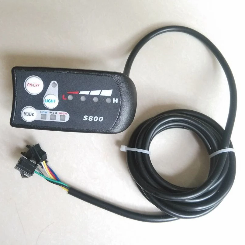
Thanks a lot for your reply. Great, that sounds promising. There isn't too much else to show of the system except the controller which is this one.

Do you think that this will isolate the battery if I join the wires?
 
D

Deleted member 4366

Guest
That control panel isolates the battery (remotely) so you have nothing to worry about joining the two wires directly together that were on the switch. Effectively, what you have is the same as that Lunacycles switch, so you don't need another one.
 
  • Like
Reactions: Ryds

Ryds

Finding my (electric) wheels
Jun 14, 2017
9
0
46
Southern Sweden
That control panel isolates the battery (remotely) so you have nothing to worry about joining the two wires directly together that were on the switch. Effectively, what you have is the same as that Lunacycles switch, so you don't need another one.
Hey d8veh,

I connected the two wires but no joy. Before taking the lock apart the voltage at the main battery connection read 2 volts. When I took the fuse out and read the voltage across there it read 32.5v

Now that I've joined the wire, I'm surprised to see that the main connection still reads 2v, whilst across the fuse still reads 32.5.

I've taken apart the main battery connection and see no problems with it. I notice the the black negative wire snakes down inside the casing, do you think there could be an issue at the point where it joins the battery pack?
 
D

Deleted member 4366

Guest
You need to charge the battery. The BMS has kept the charge port open but switched off the discharge because that voltage is too low. The charger should charge it to 42v, assuming that it's a 36v battery.
 
  • Like
Reactions: Ryds

Ryds

Finding my (electric) wheels
Jun 14, 2017
9
0
46
Southern Sweden
Aha, ok. I'll leave it on overnight and test in the morning. Yep it is a 36v. I've just plugged it in to charge and one thing I notice is that the charger has a fan inside. When I plugged it in the fan came on for only about one second, I seem to remember it staying on throughout the charge process. I'll keep an eye on it tonight. Thanks again!
 

Ryds

Finding my (electric) wheels
Jun 14, 2017
9
0
46
Southern Sweden
You need to charge the battery. The BMS has kept the charge port open but switched off the discharge because that voltage is too low. The charger should charge it to 42v, assuming that it's a 36v battery.
No joy i'm afraid. The charger connection on the battery reads 1.0v, the output connectors read about 2v, but when I take the fuse out the connectors for the fuse read 32v.

When the charger is connected the output connectors read 42 volts.

Do you think the BMS is broken? With my extremely limited knowledge I'm thinking it might be worth taking the whole thing apart to check that the negative cable is secure - what do you reckon?
 
D

Deleted member 4366

Guest
Yes, it's time to open it up. You need to get to the BMS, which you'll probably see at one end or the other. Slide the contents out of the case until you have full access to it. You'll probably have to peel off some tape or heatshrink to get full access.

You should unplug the multi-pin connector, and with your black probe on the ground from the cell pack, measure the voltage on each pin. Normally, there's little slots on the edge of the connector where you can put your red probe. You need 10 results in steps of about 3.5v. If you only get 9 steps, the 10th is on the red battery wire.

Post the results here, then we can tell you what to do next.
 
  • Like
Reactions: Ryds

Ryds

Finding my (electric) wheels
Jun 14, 2017
9
0
46
Southern Sweden
Yes, it's time to open it up. You need to get to the BMS, which you'll probably see at one end or the other. Slide the contents out of the case until you have full access to it. You'll probably have to peel off some tape or heatshrink to get full access.

You should unplug the multi-pin connector, and with your black probe on the ground from the cell pack, measure the voltage on each pin. Normally, there's little slots on the edge of the connector where you can put your red probe. You need 10 results in steps of about 3.5v. If you only get 9 steps, the 10th is on the red battery wire.

Post the results here, then we can tell you what to do next.
Ahh, I was worried about that! I think that's gonna be a bit too much for me. I've spent the past week reading all about batteries, I don't come from any sort of electronic background, and all the reading I've done has kinda convinced me not to mess around with the insides of them!

I'm gonna send it off to a company I've found in Stockholm to renovate but seriously I really appreciate your help and advice and I'm glad I've found this community! :)
 
D

Deleted member 4366

Guest
It's not difficult. Anybody can do it. All you need is a digital multi-meter and the ability to follow simple instructions. Your battery is scrap otherwise.
 

Ryds

Finding my (electric) wheels
Jun 14, 2017
9
0
46
Southern Sweden
Ok, I'll try!

One quick question, by ground, you mean the black (negative) wire right? And I touch the multimeter to where it comes out of the battery?
 
D

Deleted member 4366

Guest
Yes, but you have to get it on the cell-pack side of the BMS because the BMS is a switch that disconnects it on the output side. Only the negative is switched by the BMS. The positive goes straight to the output terminal. Here's a schematic that might help: