Hailong HL1 36v Batteries - on/off switch - yes or no?

Woosh

Trade Member
May 19, 2012
20,043
16,741
Southend on Sea
wooshbikes.co.uk
in order to get to the track you want to cut, you have to dismantle the BMS. It's a no no for 99% of users regardless how good they are with their soldering iron.

If I absolutely need a switch on my battery, I would just cut the black wire that goes to the battery out and insert a 15A switch where the cut is. The spark is impressive looking but if you have blade contacts (which is the case on 99% of Hailong batteries), the energy dissipated is tiny.
 

saneagle

Esteemed Pedelecer
Oct 10, 2010
6,078
2,871
Telford
in order to get to the track you want to cut, you have to dismantle the BMS. It's a no no for 99% of users regardless how good they are with their soldering iron.

If I absolutely need a switch on my battery, I would just cut the black wire that goes to the battery out and insert a 15A switch where the cut is. The spark is impressive looking but if you have blade contacts (which is the case on 99% of Hailong batteries), the energy dissipated is tiny.
You can't use a normal 15A switch. The inrush burns the contacts in no time at all. The only ones that gave/give any significant life were/are the key-switches that have sliding contacts. IIRC, they switch on the positive red wire. They're probably only good up to 36v because the inrush from the higher voltages is fearsome.

You could mount it on a bracket or plate using the two 5mm fixing threads.


Az.

Esteemed Pedelecer
Apr 27, 2022
1,823
821
Plymouth
Speaking of intellectual masturbation... did you take into account warranty or not?
 

Cadence

Pedelecer
Feb 23, 2023
228
177
Yes, you can charge through the pins on the multipin connector. I sometimes solder two wires to two pins of one of these things, which you can break to whatever length or number of pins you want. Check that your pins are the more common 2.5mm pitch, otherwise you have to look for pin header with the matching pitch:

Considering the low cost of balancing. I would do it before I'd buy a new BMS, and you can then test whether the balanced battery works OK, if it doesn't, you can temporarily bridge the B- to the P-, which by-passes the output Mosfets. That'll be OK for one cycle to test whether the problem goes away. If that doesn't solve it, there's a cell problem, so no point in wasting money on a new BMS.
Thanks once again for your time and free advice - it's what makes this forum so interesting and is much appreciated.
I just need to open the battery (again!) to check the pitch of the pins on the BMS connector before I order one of those connector strips. Just so I've got this right, I can make up a 2 pin "plug" to solder wires to from a charger. I assume that the (+) plugs into the low cell group socket on the BMS connector and the (-) goes into the cell group socket next to it down in line towards the black wire?
I have an old phone charger which is 5v. 750mA. which I can cut the mini-usb plug off, identify +/- and solder to the plug?
It's then a case of monitoring the charge until the low cell group matches the others at 4.2v. and the cumulative is 42v.?

If this works and I don't need to keep opening the battery to balance it I will have two Yose Power batteries, so the need for a new one diminishes.
However, if I did need another with branded cells (and thus no switch on it) the key-switches you have linked to seem a very good idea - unless I have missed something. Assuming the right size one could substitute the existing lock in the new battery. Not only does it isolate the discharge connector for fitting, but it also ensures that you can't switch on without locking the battery in place.
 

saneagle

Esteemed Pedelecer
Oct 10, 2010
6,078
2,871
Telford
Thanks once again for your time and free advice - it's what makes this forum so interesting and is much appreciated.
I just need to open the battery (again!) to check the pitch of the pins on the BMS connector before I order one of those connector strips. Just so I've got this right, I can make up a 2 pin "plug" to solder wires to from a charger. I assume that the (+) plugs into the low cell group socket on the BMS connector and the (-) goes into the cell group socket next to it down in line towards the black wire?
I have an old phone charger which is 5v. 750mA. which I can cut the mini-usb plug off, identify +/- and solder to the plug?
It's then a case of monitoring the charge until the low cell group matches the others at 4.2v. and the cumulative is 42v.?

If this works and I don't need to keep opening the battery to balance it I will have two Yose Power batteries, so the need for a new one diminishes.
However, if I did need another with branded cells (and thus no switch on it) the key-switches you have linked to seem a very good idea - unless I have missed something. Assuming the right size one could substitute the existing lock in the new battery. Not only does it isolate the discharge connector for fitting, but it also ensures that you can't switch on without locking the battery in place.
I'm not sure you can use it as the battery lock unless you have the same type already, but without the wires and switch. You can still use it separately in the positive battery wire, by cutting it and extending it to wherever you can mount the switch.
 

Woosh

Trade Member
May 19, 2012
20,043
16,741
Southend on Sea
wooshbikes.co.uk
You can't use a normal 15A switch. The inrush burns the contacts in no time at all.
How many times do you think it takes before the switch is burned?
Years ago, before the switch was made electronic soft switch, battery switch was simply in-line with the fuse.
 

Cadence

Pedelecer
Feb 23, 2023
228
177
If anyone is following my quest to solve the battery problem, I opened it up again to measure the BMS pins. They are 2mm pitch and about 5mm long, so those suggested by @saneagle are too big:-

IMG_20240909_183609284_BURST000_COVER.jpg

After a quick search I found a UK supplier of a male pin-header which I can make a 2 pin connector from:-
It should arrive in a couple of days, and I'll post some photos when I've made up a cable to connect to a phone charger for peer review before going any further.
 

Ghost1951

Esteemed Pedelecer
Jun 2, 2024
1,130
379
I think you will succsessfully re-balance this battery. Following with interest.
 

saneagle

Esteemed Pedelecer
Oct 10, 2010
6,078
2,871
Telford
How many times do you think it takes before the switch is burned?
Years ago, before the switch was made electronic soft switch, battery switch was simply in-line with the fuse.
They can weld together on the first attempt. It depends exactly which switch.
 

saneagle

Esteemed Pedelecer
Oct 10, 2010
6,078
2,871
Telford
If anyone is following my quest to solve the battery problem, I opened it up again to measure the BMS pins. They are 2mm pitch and about 5mm long, so those suggested by @saneagle are too big:-

View attachment 59720

After a quick search I found a UK supplier of a male pin-header which I can make a 2 pin connector from:-
It should arrive in a couple of days, and I'll post some photos when I've made up a cable to connect to a phone charger for peer review before going any further.
You can also use jumper leads, which are slightly more convenient and can be used to make cell voltage measurement easier. Cut them in half to have male and female:
 

Cadence

Pedelecer
Feb 23, 2023
228
177
I think you will succsessfully re-balance this battery. Following with interest.
Thanks! I really want to explore the possibilities and learn along the way. Hopefully it might help others that experience similar problems. I will post photos in stages to make sure I'm not going to burn the shed down! :D
I think it's a shame there isn't a "sticky" function or an FAQ section for these sort of things. How many times do we get someone asking "why is my battery dead" or the dreaded "how can I de-restrict my bike"?
Having said that, I do like to read the replies from saneagle, Nealh, Woosh and others - even on things I'm not really interested in. The advice is invaluable and the occasional dry humour is hilarious. Where would we be without these people giving their time and knowledge freely? Get well soon @saneagle.:)
 
  • Like
Reactions: Ghost1951

saneagle

Esteemed Pedelecer
Oct 10, 2010
6,078
2,871
Telford
Get well soon @saneagle.:)
I am well! Are you implying something?

Seriously, though, it's very satisfying when members actually do the tests we recommend. What you've done and shown, not just in this thread, explores the problem, bringing info and knowledge to all who will read it. Your knowledge is improving all the time, which you'll be able to pass on too.

In other words, the knowledge comes from people that do stuff, not just talk about it.
 
Last edited:

Cadence

Pedelecer
Feb 23, 2023
228
177
I am well! Are you implying something?
Not at all. This is what you posted yesterday in the Argos folder thread:-

"I made good progress today after getting out of hospital yesterday pretty well cured. I will continue the thread shortly, but I've encountered a bit of a setback that I'll explain in another thread."

I mis-read that to mean a medical setback, but now realise that you were perhaps referring to your throttle wiring conundrum posted in another thread.
Anyway, the sentiment is sincere - stay well! :)
 

saneagle

Esteemed Pedelecer
Oct 10, 2010
6,078
2,871
Telford
Not at all. This is what you posted yesterday in the Argos folder thread:-

"I made good progress today after getting out of hospital yesterday pretty well cured. I will continue the thread shortly, but I've encountered a bit of a setback that I'll explain in another thread."

I mis-read that to mean a medical setback, but now realise that you were perhaps referring to your throttle wiring conundrum posted in another thread.
Anyway, the sentiment is sincere - stay well! :)
It was a joke. If somebody is healthy and you tell them to get well soon, it has a special meaning. By my joke, I wanted to give the impression that I am indeed totally well. I really appreciate your comments and concern. Sorry my joke backfired a bit. I admit that when I wrote it, I saw the possibility of it getting misinterpreted, so it's my fault.
 
  • Like
Reactions: Cadence

Ghost1951

Esteemed Pedelecer
Jun 2, 2024
1,130
379
I've lost count of the number of times misunderstandings occur when people type things and what they intended doesn't quite come over. Our species depended on face to face comms for at least a hundred thousand years and we can see how the joke or remark is going down and quickly correct with a twitch of the facial muscles if it's going wrong, or the other person is getting bored or doesn't understand. Not so on the web.
 
  • Like
Reactions: Cadence

Cadence

Pedelecer
Feb 23, 2023
228
177
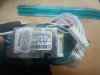
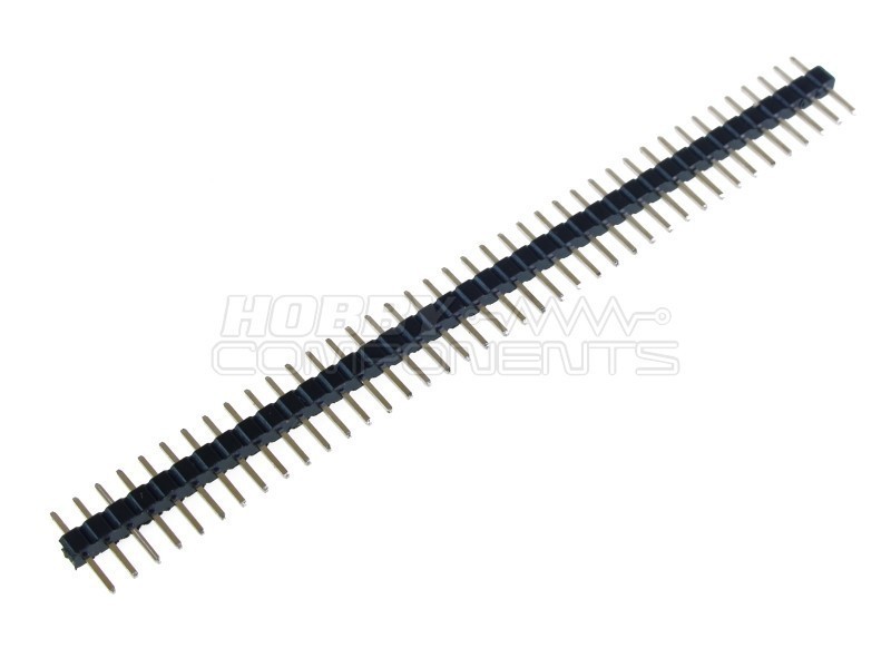
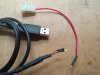
The pin header strip arrived today, so I've made a 2-pin charging cable from a USB lead that came with an old phone charger. Having stripped back the outer insulation and shielding I was able to confirm my assumption that red is positive and black is ground with my multi-meter :-

IMG_20240911_133534413.jpg

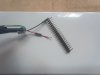
My eyesight and hands reminded me that it is many years since I've done any soldering on this small scale! Fortunately some heat-shrink tubing hides the worst of it. Unfortunately I dwelled a bit too long and the plastic spacer softened sufficiently to make the pins loose. Fixed with a drop of superglue, I just hope that the 2mm pitch has been maintained - we'll see:-

IMG_20240911_142930882.jpg

I would be grateful if those more knowledgeable and experienced than me will confirm that the red(+) pin goes in the low- voltage cell socket on the BMS connector, and the black(-) goes in the next one immediately down - i.e. towards the black ground socket at the end?
While I had the soldering kit out I also made up a single pin lead with a block connecter at the other end, which will make testing individual sockets on the BMS connector safer and more convenient.

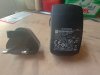
I have two mains adaptors, both with suitable USB sockets. One is a phone charger labelled 5v. 750mA. Can someone advise approx. how long it would take to lift the low cell group from 3.4v to match all the others at 4.2v?
The other is a Garmin adaptor for a Sat Nav. It is labelled 5.35v. 2.0A MAX. I'm assuming that this will charge quicker, but is that safe or desirable?
IMG_20240911_143347616_HDR.jpg

I really would welcome some assurance that I've got all this right before I "light the blue touchpaper" :eek: , but as I'll be doing it outside that will have to wait for the weather to improve.
 
Last edited:

Ghost1951

Esteemed Pedelecer
Jun 2, 2024
1,130
379
The first thing that strikes me about the plan is that the charger you are going to use is a 5v one and you must not let the cell bank you are charging up go above 4.2v. I am sure you know this, but I will say it anyway for fear someone comes along in a year's time and gets the wrong idea.

When I said I had brought a weak group of cells back to balance, I made the point that I used a lithium cell charger which cuts off at 4.2 volts - it actually cuts off at 4.19, so there was no way my charging would take the cell group over voltage.

This means you will need to supervise it very closely if you go ahead.

I have not used the BMS connection as you are going to do. I tagged temporary leads onto the affected cell group, so I have no experience of using the BMS lead.

However, you can be sure whether you have the right leads chosen for your connection by using your multi- meter. Measure the voltage before you start and the polarity of course. You will soon find the affected group with its low voltage. Double check you have the polarity right.

My out of balance cells took a long time to catch up, but I was using a lower power charger than you have.
 

saneagle

Esteemed Pedelecer
Oct 10, 2010
6,078
2,871
Telford
You're correct that the ground (black) goes to the pin one down from the one that shows low voltage. The red obviously goes to the pin adjacent to it going in the direction of higher voltage.

Before you connect, check your two pins with a voltmeter to see that they're definitely the correct way round.

The charger I can see is 2A, which is the normal charging current, so perfectly OK. I normally do it with 1A because I don't want it to happen too quick when I forget to check how it's going.

You can calculate the time from the battery capacity. Say it were a 10A battery, then charging that cell group from 3.1v to full would take 5 hrs (10÷2). At 3.8v You're about 30% down. Roughly, each 0.1v is 10%, so 0.3x10÷2 = 1.5 hrs. Substitute whatever your battery's capacity is and the cell group's present voltage is in that equation.

One thing to watch out for is that from 4.1v, the voltage will accelerate upwards, not take the the same time as it did from 4.0 to 4.1, so be ready for that, otherwise you'll overcharge.

It would be interesting to record the time for it to charge because it'll give you a good estimate of how much capacity it was missing.

Obviously, if the voltage doesn't keep rising, abandon the operation because there would be something wrong with that group and the energy from the charger must ho somewhere.
 

Cadence

Pedelecer
Feb 23, 2023
228
177
Thanks for the replies guys, I really wouldn't be attempting this without your help. I realise that the charger is capable of overcharging and intend to keep a close eye on proceedings to avoid going over 4.2v. It's a 13 Ah battery so using saneagles' calculation it should take just under 2 hours using the 2A charger.

I will be stopping the charge initially at 10 minute intervals to see what's happening. Obviously I'll disconnect to do so, but do I need to wait for things to "settle" for a while to avoid false readings? I'm thinking of then doing 15 minute intervals until 4.0v. is reached, then every couple of minutes to reach 4.2v. when I should hopefully also have a full 42 volt battery.
 

Cadence

Pedelecer
Feb 23, 2023
228
177
After the very welcome input from Ghost1951 and saneagle I've been giving this a bit more thought. Although I'm sure it would work, I'm a little concerned that I might not be able to accurately charge up to 4.2v. with the Garmin 5.35v. charger. I certainly don't want to complicate things by inadvertently over-charging. Ghost1951 mentioned that he used a lithium cell charger that cuts off at 4.2v. A search found this:-


It cuts off at 4.2v. and has red and green LED's just like a normal e-bike charger. At 1A I'm expecting it to take twice as long as the Garmin 2A charger but that's probably no bad thing.
There is also an optional female DC socket to use with the charger's DC plug. It has polarity-marked screw terminals and will be a doddle to fit to my improvised charging cable after cutting off the USB. I therefore won't need to cut the DC plug off the new charger's lead and I can take cell voltage readings from the DC socket terminal screw heads . It's altogether safer and more convenient .
The only downside that it is coming from China (what doesn't these days!) so I will probably have to wait around 2 weeks for it to arrive.
 
  • Agree
Reactions: Ghost1951