Battery current measurement

Sector

Pedelecer
Mar 5, 2007
102
0
Leicestershire Le8
I wanted to measure the current consumption on my bikes, but didn't want to disturb the wiring between the battery and the motor. I thought I might do it by removing the fuse and replacing it with an adpater that would bring two wires out for the current measurent. I took the fuseholder cap from my oldest battery and removed the plastic from the end of the cap. I soldered a wire to the end of the cap, then I drilled a hole in the cap big enough to pass a wire through.

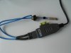
I tried to detach one of the shiny chrome end caps from a glass fuse, but broke the glass every time. Then I found an old mains 13 amp fuse, and that proved to be more robust. I removed one cap and drilled a hole through the other end of the fuse. I passed the blue wire through and soldered the wire at the end. I threaded a spacer on the wire to bring the assembly to the same length as a glass fuse. I also installed the spring from the fuseholder cap.

R0012102_L.jpg

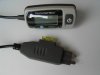
I connected an Avo with a high current shunt, via an in-line fuseholder and 20 amp fuse, and was able to measure battery current with the adapter.

The downsides of this method are:
- The AVO and shunt are big and it was difficult to hang them on the bike.

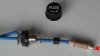
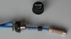
- Its a pity I had to destroy the fuseholder cap. Does anyone know where I can get another like the one at the top of the photo?

- As with all battery modifications, there are risks involved.

Part two of this tale will follow in the next message.
 

flecc

Member
Oct 25, 2006
53,469
30,775
That looks like the fuse holder cap from an eZee battery Pete? If so, PM me an address and I'll pop a spare one that I have into the post for you.
.
 

Sector

Pedelecer
Mar 5, 2007
102
0
Leicestershire Le8
Maplins Ammeter

Maplins Item N48Cy is a "Car Current Tester".

Automotive Current Tester > Maplin

It is intended to be connected in place of a car-type fuse as a check of which circuits are using current. This, of course, was what my battery fuseholder modification was trying to do for round glass type fuses.

The Maplin unit consists of an ammeter, rated for 20 amps for 10 seconds. The shunt seems to be located inside the dark grey item, with thin wires connecting to the remote digital display. The unit has a built-in socket for flat blade car fuses. You can see the yellow fuse in its socket in the picture.

I bougth one of these, about £10, and found a flat-blade type 20 amp fuse to use with it. I connected the unit to my fuseholder adapter, taped the readout where it was visible on the bike frame, and went out for a ride.

R0012095_L.jpg
R0012100_L.jpg

The unit successfully indicated currents up to 14 amps on the Quando and the Chopper. Average current over these 30 minute rides was probably 4 amps or less. I don't know how close I came to burning out the shunt resistor in the Maplin unit by this disregard for the 10 second rule.

So far I'm pleased with the possibility of connecting an ammeter quickly to any of my bikes. In future I'll probably try to keep the unit for short tests only, to reduce the risk of blowing the shunt resistor.
 
Last edited:

Sector

Pedelecer
Mar 5, 2007
102
0
Leicestershire Le8
Risks

I've been thinking through the risks associated with taking up to 20 amps out through the fuseholder.

It seems to me that the biggest risk I'm running is that there will be a bad connection where I've shown the red spark in the picture.

R0012102_L_3.jpg

There is a risk that a spark at this point would melt the solder, and the wire might solder itself to the fixed contact in the fuseholder. I've got an idea to improve the situation but in the meantime I've only using the adapter with my oldest battery. That battery is on its last legs anyway. I'm considering re-celling it, and it would be no bother to replace the fuseholder at the same time.
 

Sector

Pedelecer
Mar 5, 2007
102
0
Leicestershire Le8
Re-celling

Bert,
As far as I'm aware it is not really possible to re-cell a Lithium Ion battery. Each cell has an electronic circuit called a battery managment system connected to it, actually inside the battery casing. The whole thing is just too complex to replace as a do-it-yourself project.

In contrast the older NiMh batteries are electrically very simple. The battery box just contains a lot of individual NiMh cells, with one thermistor that is used to monitor temperature during charging. NiMh cells call still be bought, although it might be difficult to obtain cells suitable for the high rate of discharge. The cells should have connecting tags already attached if possible, otherwise there will be the job of soldering connections to each cell, which might destroy some cells. Anyway there are accounts on the web of successful re-celling of NiMh batteries. The risks to life and limb come from the huge electrical current that these cells can deliver if you get the connections wrong.

It might be possible to use an Ezee Lithium Ion battery case to house NiMh cells, but I've not heard of this being done. There would be the problem that the Lithium Ion charger would not be suitable for charging the NiMh battery, so an expensive new charger would also be needed.

I've not really looked into the economics of re-celling, but I suspect that it would not save much money. It used to look attractive for Ezee batteries when new Phylion Lithium Ion batteries were failing prematurely, and new NiMh batteries were almost impossible to obtain.

My vague interest now in re-celling would really be to obtain something that can't be bought off the shelf. It would, for example, be good to have a lightweight get-you-home battery, and various attempts have been made at this idea. Alternatively there is a new type of cell that first appeared in DeWalt power tools that seems to offer possibilites. Try Googleing "A123 battery" if you have half an hour to spare.

What we really need now is for car manufacturers to really have a go at developing electric cars. Having lived with electric bikes for a few years I suspect that current ideas for cars are badly flawed and doomed to failure in current circumstances. However there should at least be rapid development of cell technology and that would be useful for electric bikes.

Pete
 
Last edited:

flecc

Member
Oct 25, 2006
53,469
30,775
You can recell the eZee lithium case with NiMh cells since both the case and fuseholder etc are identical and the eZee battery was originally NiMh, and a couple of us have done that in the past. However, there are problems in trying to do that.

The case is designed for six vertical columns of five cells each and there isn't enough space for either tags or button end cells. The only way around that is to buy tagged cells and remove the tags to leave the cell ends smooth. The cell columns can then be bound with wrapping but that leaves the contact between cells as only a pressure one which can be inadequate for high currents.

The professional way to get over that is with cells in a column jig and a hammer shaped double headed soldering iron used to heat and tin the faces of two cells at once, the cells immediately thrust into contact with the molten solder joining them. This has to be done quickly with a very high temperature soldering iron to avoid damaging the cells, which would occur with a long application of a lower temperature iron.

You can see that this is not a job for the faint hearted, and that's not the end of the problems. The general rush into lithium has meant that manufacturers scrapped the production lines for very high discharge D cells so there are next to no suitable cells available now. Many claim to be high discharge, but mostly are now only rated for 5 Amp maximum rate and that is completely inadequate on the more powerful bikes which can draw up to 20 amps to achieve their full power.

For anyone still wishing to go ahead and take the risk with cells that are available, the thermistor is mounted in the groove formed between two of the six cell columns near the top, and it's connected to the ground and centre pins of the charge XLR socket. The 30 cells wired in series are connected to both the outer XLR pins and the bike connectors. Taking the rear of the battery to be the slide mount onto the bike, the rear XLR pin is the positive charge connection and the front bike connector is that positive.

The original eZee NiMh battery thermistor is a Semitec AT-4, part number: 103AT4, Shape 2. If not available, 103AT4 Shape 1 will also work. The main specification is R = 10k, B = 3435. Semitec don't normally deal with the public directly but if requested nicely with often send one out as a free sample.

Semitec UK. Phone: 01606 871680

If there's any problem, a wide tolerance replacement is a Murata component from Radiospares, part number 188-5256, R = 10k, B= 3380.

If converting a Li-ion to NiMh, a new charger will be needed and it's thermistor cutoff circuit characteristics have to match. A suitable one that I own and has proved thoroughly reliable for the eZee battery is supplied by Powerstream in the USA.

All the details for buying that and a suitable XLR plug for it are on a page of my Torq website linked to below, though the prices shown will vary according to current exchange rates:

eZee NiMh battery charger
.
 
Last edited:

torrent99

Esteemed Pedelecer
Nov 14, 2008
395
36
Highgate, London
I've been thinking through the risks associated with taking up to 20 amps out through the fuseholder.

It seems to me that the biggest risk I'm running is that there will be a bad connection where I've shown the red spark in the picture.

View attachment 673

There is a risk that a spark at this point would melt the solder, and the wire might solder itself to the fixed contact in the fuseholder. I've got an idea to improve the situation but in the meantime I've only using the adapter with my oldest battery. That battery is on its last legs anyway. I'm considering re-celling it, and it would be no bother to replace the fuseholder at the same time.
Yes this is EXACTLY what happened to my fuseholder, dodgy connection caused smell of burning plastic! :rolleyes:

My method for measuring current and consumption (well not mine it's actually from a number of posts on Endlesssphere particularly by TylerDurden), is to use a modified plug in mains consumption meter, known as a Killawatt. These are available from maplin/ebay for around £14. A simple mod lets you power it from a 9V battery instead of the mains supply. Then you get current, voltage and KWh consumed... I keep meaning to mod mine so that the display and current measuring sections are separate....

The car current meter looks excellent though.
 

Sector

Pedelecer
Mar 5, 2007
102
0
Leicestershire Le8
Maplins Meter

Torrent99,
Thanks for letting me know about the posibilities with the Maplin power meter. Are you referring to the Maplin L61AQ item?

Plug-In Mains Power and Energy Monitor > Maplin

I might just have to point the bike towards Maplins tomorrow. Looks like its going to be a nice day for a ride.

I managed to find the following on Endless Sphere:

Endless-sphere.com • View topic - Dewalt 36V (inside the charger)

Are there any other pages I ought to look at before I start modding?

Pete
 

torrent99

Esteemed Pedelecer
Nov 14, 2008
395
36
Highgate, London
Torrent99,
Thanks for letting me know about the posibilities with the Maplin power meter. Are you referring to the Maplin L61AQ item?

Plug-In Mains Power and Energy Monitor > Maplin

I might just have to point the bike towards Maplins tomorrow. Looks like its going to be a nice day for a ride.

I managed to find the following on Endless Sphere:

Endless-sphere.com • View topic - Dewalt 36V (inside the charger)

Are there any other pages I ought to look at before I start modding?

Pete

That's the one! You can sometimes find the exact same model on Ebay for much cheaper.

The best thread on ES is:

Endless-sphere.com • View topic - Kill-A-Watt hack job

However, the circuit board in the pictures didn't match mine. But the mod is simple:

1) Cut/desolder one leg of the large resistor.
2) Solder in the 9V battery connector across the "large" capacitor to apply voltage to the voltage regulator and hence power the kill-a-watt.

I linked mine up by using some leads built from a combination of "kettle" plugs/sockets and ordinary 13amp plugs/sockets. But that was for a temporary set up.

For a more permanent set up you could:
1) Remove the 13 amp plug/socket arrangement & solder directly in to an in-line adaptor.
2) Extend the grey ribbon cable in the unit to allow you to mount the display/buttons remotely from the shunt/sensor.
3) Put all of it in some nice waterproof boxes.

Cheers

Steve
 

rog_london

Esteemed Pedelecer
Jan 3, 2009
764
2
Harrow, Middlesex
I must be missing something here....

I've followed this thread, but at the back of my mind something was nagging....

This device from Maplins is designed to measure watts, volts, VA, frequency, current, power factor and total power consumed (I've had one for some time). In other words, it's all about AC mains. What exactly is it being used for here? It's not a DC device and if it is capable of measuring a DC supply it's not calibrated accordingly, so it would produce a completely erroneous reading.

If you are in fact using it for its designated purpose, why would you want to run it off a 9V battery? If you are doing that and measuring the bike battery current, how do you interpret the readings?

Rog.
 

Mussels

Esteemed Pedelecer
Jun 17, 2008
3,207
8
Crowborough
I've followed this thread, but at the back of my mind something was nagging....

This device from Maplins is designed to measure watts, volts, VA, frequency, current, power factor and total power consumed (I've had one for some time). In other words, it's all about AC mains. What exactly is it being used for here? It's not a DC device and if it is capable of measuring a DC supply it's not calibrated accordingly, so it would produce a completely erroneous reading.

If you are in fact using it for its designated purpose, why would you want to run it off a 9V battery? If you are doing that and measuring the bike battery current, how do you interpret the readings?

Rog.
A meter tends to work the same way no matter what it is measuring, the switches on the front are so the meter can convert the input to something it can read. So a meter designed to read mains AC voltage can fairly easily* be modified to read DC current if necessary.

* Some will be much easier to tweak than others which is why one has been singled out here.
 

rog_london

Esteemed Pedelecer
Jan 3, 2009
764
2
Harrow, Middlesex
A meter tends to work the same way no matter what it is measuring, the switches on the front are so the meter can convert the input to something it can read. So a meter designed to read mains AC voltage can fairly easily* be modified to read DC current if necessary.

* Some will be much easier to tweak than others which is why one has been singled out here.
Hmm. I've been an electronics engineer for far too many years to be able to accept that one I'm afraid. At the very least the calibration for DC measurement would be well out.

What I'm saying is that it's not just a matter of persuading it to wake up on a low voltage DC supply instead of using the large mains dropper resistor. That's the easy bit. Measuring, for example, AC voltage would involve a rectifier, and you never get a volt-for-volt conversion, as a full-wave rectifier on a 230V AC circuit will give you close to 300 volts DC, and while most AC meters (probably including the Maplin unit) are really DC meters with a rectifier, any DC voltage or current measurements you make will be much higher than what the display will let you believe as the unit will have no facility for the dual-calibration that an AC/DC multimeter will have. Does the Maplin unit allows you to recalibrate by the necessary considerable margin?

Even if it does, you'd need a good deal of knowledge to make the changes, or at least a conversion chart that you can refer to. Most people wouldn't have access to the necessary test gear to produce that or recalibrate the unit.

Personally I think it would be much easier to use a simple DC meter and a home-made shunt. At least then you start with something designed for the job, and which would be much easier to deal with. You'd still need to calibrate and tweak the shunt, but with an appropriate PSU and test gear such a shunt could be a piece of steel bar and calibration would involve a bit of filing or hacksawing.....

Having taken a look on EndlessSphere they don't mention the Maplin unit, but something similar designed for the US market.

Better you than me, therefore, if you're planning on going down that route!

The automotive measuring unit (also from Maplin, I think) mentioned at the beginning of this thread sounded like a better idea.

Rog.
 
Last edited:

Mussels

Esteemed Pedelecer
Jun 17, 2008
3,207
8
Crowborough
Better you than me, therefore, if you're planning on going down that route!
I don't have that much time on my hands, I'd just buy something designed for the job in the first place.
I just took the info at face value and assumed that someone with the right knowledge has made and documented the chages, my post was over simplified but I didn't know you were familiar with how the meters worked.
I stopped working with components and meters many years ago and my post was based on moving coil theory, I'm quite happy to take your word for it that the Maplin idea is impractical.
 

rog_london

Esteemed Pedelecer
Jan 3, 2009
764
2
Harrow, Middlesex
I don't have that much time on my hands, I'd just buy something designed for the job in the first place.
I just took the info at face value and assumed that someone with the right knowledge has made and documented the chages, my post was over simplified but I didn't know you were familiar with how the meters worked.
I stopped working with components and meters many years ago and my post was based on moving coil theory, I'm quite happy to take your word for it that the Maplin idea is impractical.
....and I should get out more, I know!

Rog.
 

torrent99

Esteemed Pedelecer
Nov 14, 2008
395
36
Highgate, London
....and I should get out more, I know!

Rog.
I see what you're saying RE: the AC vs DC measurement...

I'm not sure coz I don't have the meter in front of me, but I think that Maplin meter does notice the DC and takes it into account (I seem to remember it displaying DC on one of its screens). Also, when showing voltage it appears to read within about 0.5V (for a 42V voltage) of what my multimeter shows, I assumed the error was due to the general noddyishness of the meter and the fact that it isn't normally used for measuring such small voltages. [I suspect the electronics of the gadget are designed to be quite general purpose rather than just a mains meter]. I'll have to plug in in again & check...

There is a calibration procedure detailed on the ES website, though I haven't tried it.

RE: The alternatives, I agree it's probably far better to use a more specifically designed system (the cheapest being the Watts-up meter around £60 I believe, the acknowledged best being the Cycle Analyst). However, I did have one of these meters lying around and was curious about my power consumption....it was practically free to modify and use.
 

Sector

Pedelecer
Mar 5, 2007
102
0
Leicestershire Le8
I'm with experimentalists

Well, I've bought a Maplins meter and done the conversion. I've not had time to test it on current yet, but I can confirm that it does say DC when you put a DC voltage across the wires.

I understand that its not for everyone, but I love this kind of project. Personally I'd rather have this to play with than half a tank of petrol for the car, which is what the money might otherwise buy.

Thirty years ago I used to be a radio ham, which when I think about it was quite expensive and totally without practical benefit. Great fun at the time though. The best part was buying real ex-services gear and making it work. Beautiful silver plated coils, glass encased vacuum variable capacitors, and big transmitting valves. Marvellous.

Pete
 

Mussels

Esteemed Pedelecer
Jun 17, 2008
3,207
8
Crowborough
Well, I've bought a Maplins meter and done the conversion. I've not had time to test it on current yet, but I can confirm that it does say DC when you put a DC voltage across the wires.

I understand that its not for everyone, but I love this kind of project. Personally I'd rather have this to play with than half a tank of petrol for the car, which is what the money might otherwise buy.

Thirty years ago I used to be a radio ham, which when I think about it was quite expensive and totally without practical benefit. Great fun at the time though. The best part was buying real ex-services gear and making it work. Beautiful silver plated coils, glass encased vacuum variable capacitors, and big transmitting valves. Marvellous.

Pete
I used to get paid to fix the old services radio equipment, I was glad to see the back of it. :D