Argos £245 folding Bike Improvements

saneagle

Esteemed Pedelecer
Oct 10, 2010
6,061
2,860
Telford
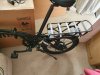
I've started with some improvements to make the bike a bit more useful for me. Its main problems are the too low gearing and the lack of torque. The weight is also a bit on the high side. Most of the weight is in the frame, so not much can be done about it. If you were serious, you could change the crank to hollowtech, chuck the mudguards and heavy rack and change the seat to a lightwight one, which would get it down to about 22kg. Is it worth it?

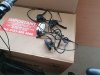
Step 1 : change the 6-speed 14/28 freewheel to a 7-speed 11/30 DNP one. Umfortunately I've never seen a 6-speed with 11T top gear, so it has to 7-speed.
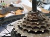
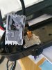
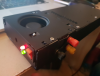
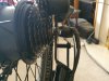
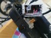
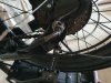
This is the starting point. There's about 2.5mm between the edge of the freewheel and the frame. Note also that the motor cable goes directly forward from the axle, so is sitting on the edge of the hole, which could cut into it instead of the slo. That's because they've pulled the cable too tight instead of letting it loop downwards to stop water going in.:
59485


59487
 

saneagle

Esteemed Pedelecer
Oct 10, 2010
6,061
2,860
Telford
When I put the new freewheel on, it looks the clearance to the frame will not be enough.
59488

I therefore added a 1mm thick washer. That extra 1mm on the axle width made it quite difficult to install the wheel because the frame is very stiff. You don't get that on frames for bigger wheels because the stays are longer and more flexible. A standard 12mm washer is too big to go inside the freewheel, so you either need to grind it down or get one with a non-standard smaller O/D:

59489

The wheel is reinstalled. There does appear to be more than 1mm gap between the freewheel and the frame, so maybe I didn't need the washer. I'll check next time I take the wheel off.
59491

I'll test it later. While I have my tools out, I want to have a look at the controller.
 

saneagle

Esteemed Pedelecer
Oct 10, 2010
6,061
2,860
Telford
Step 2 - more torque
The battery is held into the rack with 5 screws, then there are 4 screws holding the cover on the controller box:
59492

Now I can see the reason for the lack of torque. This is the lowest I've ever seen by far - 8 amps maximum, 4 amps rated power written on the controller. I wonder why it's so low. The battery weighs 2.3kg, so I calculate it must be a 30 cell one if 18650s or 20 cells if 21700s. The screws are all sealed with hot-melt glue, so I don't really want to open it to see what cells they are. Whatever they are, they should be able to manage at least 12 amps. I didn't notice any significant sag when climbing at 8 amps, so I'd have reasonable confidence in increasing it a bit. I might increase it in stages to see how much sag I get, which is an indication of how hard the cells are being pushed.

59494
 

Ghost1951

Esteemed Pedelecer
Jun 2, 2024
1,122
377
Oh - I AM VERY interested in what you are doing here. Even if I don't change anything, I am keen to know how it is made and put together. Shame you don't want to open the battery, but I certainly understand why.
 
  • Like
Reactions: Peter.Bridge

saneagle

Esteemed Pedelecer
Oct 10, 2010
6,061
2,860
Telford
My first plan was to solder the shunt in the controller. I took the end-plate off in the hope that I would see the shunt grinning at me, but all I saw was uniform grey silicone:
59501

I hacked it a bit before taking that photo. I then did a bit of digging, but didn't come across it.

59502

so I decided, rather than dig the whole thing out, to call it quits and fit a KT controller. I went through all my stock, but the only ones I have in that size are a bluetooth one (very rare) and a 48v only 14A one, so I just ordered a few 36v/48v 15A ones, which will take a couple of weeks to arrive. There was a squarewave one on Amazon Prime with the moulded connectors for £25, but I think I'd rather wait for a sinewave one.
 

Ghost1951

Esteemed Pedelecer
Jun 2, 2024
1,122
377
How does soldering the shunt in the controller increase performance? I have heard of it, but don't know how it works, and I am wondering how it might affect the reliability of whatever mosfets are in the box already if power is increased.

It might be - probably really is - that the mosfets are specced for whatever it is producing right now. On the other hand, maybe the controller was originally designed for a more normal level of output - say 12 or 15 amps and that it has been crippled for this particular application. Are the shunted controllers you have used before as reliable as they were before the modification?
 

Ghost1951

Esteemed Pedelecer
Jun 2, 2024
1,122
377
I am looking forward to the updates and am glad you are doing the upgrades. Very entertaining from my point of view.
 

portals

Esteemed Pedelecer
Jul 15, 2022
528
161
How does soldering the shunt in the controller increase performance?
Putting a small amount of solder across shunt allows more current to flow so at lower speeds so you'll get better torque/performance going up hills.
 

portals

Esteemed Pedelecer
Jul 15, 2022
528
161
@saneagle - what is the controller spec for the other red/black Argos ebike you bought or is that for next weekend? :) ? It looks like it was a great deal and I kinda wished I'd bitten now ;-)
 
  • Like
Reactions: Peter.Bridge

saneagle

Esteemed Pedelecer
Oct 10, 2010
6,061
2,860
Telford
How does soldering the shunt in the controller increase performance? I have heard of it, but don't know how it works, and I am wondering how it might affect the reliability of whatever mosfets are in the box already if power is increased.

It might be - probably really is - that the mosfets are specced for whatever it is producing right now. On the other hand, maybe the controller was originally designed for a more normal level of output - say 12 or 15 amps and that it has been crippled for this particular application. Are the shunted controllers you have used before as reliable as they were before the modification?
The controller measures the voltage drop across the shunt to calculate and control the current. It uses Ohm's law V=IR. the shunt typically has a value of about 0.01 Ohms, which the controller uses for its calculation. If you change the resistance of the shunt, the controller doesn't know, so it calculates incorrectly. basically, if you reduce the resistance of the shunt by 30%, the controller will allow 30% more current than what it did before. You do that by adding a thick gob of solder along its length to reduce that part to zero resistance.

There's a photo of one I did here in post #9:
 
  • Like
Reactions: Ghost1951

saneagle

Esteemed Pedelecer
Oct 10, 2010
6,061
2,860
Telford
@saneagle - what is the controller spec for the other red/black Argos ebike you bought or is that for next weekend? :) ? It looks like it was a great deal and I kinda wished I'd bitten now ;-)
I didn't look. I had health problems at the time it arrived, so I couldn't do much, and the bike was donated the same day. It visits me every week, but we're busy doing other stuff. Maybe in the future we can do something with it, but the owner is very happy with it as it is. By comparison with other bikes, I'd say that it has a controller that gives 12A to 15A max, and probably at the higher end if I had to bet. It didn't have any problem getting up my 14% test hill with a bit of pedalling, while as the folding bike slowed down as if it were switched off.

You should keep looking in case they come back again. Those bikes are very good. everything about it felt right. They're perfect if you want a bike for commuting, shopping and generally riding around as transport.
 
  • Like
Reactions: portals

Ghost1951

Esteemed Pedelecer
Jun 2, 2024
1,122
377
Putting a small amount of solder across shunt allows more current to flow so at lower speeds so you'll get better torque/performance going up hills.
Thanks Portals.

Yes I went away and looked it up after I posted the question. The shunt provides a measure of current which is used by the controller to estimate how much current is flowing - the shunt being a known resistance (which we now change to trick the controller. By lessening the resistance we cause the controller to supply more current than the designer intended to supply to the motor phase wires.

Unless the mosfets are built for the new 'regime' we have created, I prophesy trouble ahead.

I think if I was doing this I would carefully measure the original resistance of the shunt and decrease it slightly - in line with what I thought the mosfets would manage safely.

It looks as if the current passed by the controller would increase in direct proportion to the drop in resistance of the soldered shunt. So if the shunt was for example (and I have no idea what they really are) 10 ohms and you reduced it to 7.5 ohms with some solder, you would get a 25% increase in maximum current through the mosfets.

Te supplied controller is filled with potting compound so this would be a difficult pain in the butt to do, but since the details printed on the outside say the thing is rated for 4 amps and has a peak of 8 amps, I am inclined to think it would not take kindly running at 12 or 15 amps.

I think Saneagle has made the right choice in sending for a new controller.

EDIT

Ah - lots of new posts since I was writing that. It is therefore entirely irrelevant now.
 

saneagle

Esteemed Pedelecer
Oct 10, 2010
6,061
2,860
Telford
Thanks Portals.

Yes I went away and looked it up after I posted the question. The shunt provides a measure of current which is used by the controller to estimate how much current is flowing - the shunt being a known resistance (which we now change to trick the controller. By lessening the resistance we cause the controller to supply more current than the designer intended to supply to the motor phase wires.

Unless the mosfets are built for the new 'regime' we have created, I prophesy trouble ahead.

I think if I was doing this I would carefully measure the original resistance of the shunt and decrease it slightly - in line with what I thought the mosfets would manage safely.

It looks as if the current passed by the controller would increase in direct proportion to the drop in resistance of the soldered shunt. So if the shunt was for example (and I have no idea what they really are) 10 ohms and you reduced it to 7.5 ohms with some solder, you would get a 25% increase in maximum current through the mosfets.

Te supplied controller is filled with potting compound so this would be a difficult pain in the butt to do, but since the details printed on the outside say the thing is rated for 4 amps and has a peak of 8 amps, I am inclined to think it would not take kindly running at 12 or 15 amps.

I think Saneagle has made the right choice in sending for a new controller.

EDIT

Ah - lots of new posts since I was writing that. It is therefore entirely irrelevant now.
You can predict the output current fairly accurately without having to resort to measurement. Shunt wire has a resistance of x Ohms per metre. If you shorten the length, the resistance decreases in direct proportion. When you solder it, the bit you soldered reduces the resistance to zero, so it's the same as cutting down the length. If you solder 25% of the length the resistance is reduced by 25% and the current increases by 25% - simple physics.

On one controller, I replaced the shunt with a 10cm length of 14g battery wire, which has the same resistance as the shunt. You can then adjust the current by changing the length of the wire.

Some controllers have solid state shunts. You can change their value by soldering another one over the top of it. Using your schoolboy physics, 1/R = 1/R1 +1/R2

From my experience of using a lot of different controllers, the small box ones can handle at least 18A max, even with their crappy MPSFETs. Onces with decent MOSFETS can go higher. Whatever you do, you have to be mindful that they can't hold maximum current for a prolonged period, which is why the rating is always half the maximum. It's not an exact science. You have to find out how hot your controller gets in different circumstances.
 

portals

Esteemed Pedelecer
Jul 15, 2022
528
161
The controller measures the voltage drop across the shunt to calculate and control the current. It uses Ohm's law V=IR. the shunt typically has a value of about 0.01 Ohms, which the controller uses for its calculation.
This is also how the cheap Voltmeter/Ammeters you see on ebay calculate the current, they use I=V/R to display current across a shunt.

I built one few yrs back to measure the current consumed by my slot car track for LED strips, Arduinos and other accessories and wired a GND / 5V / 12V busbar under track repurposing an old dell desktop ATX power supply that can provide a lot of current on both rails. It has a rotary switch giving off / 5V rail / 12V rail / both 5V+12V rails.

59506

59505

59504

:)
 

Attachments

egroover

Esteemed Pedelecer
Aug 12, 2016
1,031
614
57
UK
I didn't look. I had health problems at the time it arrived, so I couldn't do much, and the bike was donated the same day. It visits me every week, but we're busy doing other stuff. Maybe in the future we can do something with it, but the owner is very happy with it as it is. By comparison with other bikes, I'd say that it has a controller that gives 12A to 15A max, and probably at the higher end if I had to bet. It didn't have any problem getting up my 14% test hill with a bit of pedalling, while as the folding bike slowed down as if it were switched off.

You should keep looking in case they come back again. Those bikes are very good. everything about it felt right. They're perfect if you want a bike for commuting, shopping and generally riding around as transport.
The 360 quid Pulse MTB has a lishui lsw06-hlk1cfsb controller built into the battery base and is rated up to 15a. Here's a pic I have found which is identical to mine on the bike (my pics only show half of the info as its attached to the bike)

sterownik_1.jpg
 

saneagle

Esteemed Pedelecer
Oct 10, 2010
6,061
2,860
Telford
The 360 quid Pulse MTB has a lishui lsw06-hlk1cfsb controller built into the battery base and is rated up to 15a. Here's a pic I have found which is identical to mine on the bike (my pics only show half of the info as its attached to the bike)

View attachment 59508
Thanks for that. Also good to know I don't need to re-calibrate the power meter in my bum.
 

saneagle

Esteemed Pedelecer
Oct 10, 2010
6,061
2,860
Telford
This post is duplicated from my other thread about this bike because it should be part of this thread.

I changed the levers to Tektro ones because one had a long cable to reach the new controller. Legal throttle added to get that instant full power without having to go up and down through the buttons on the LCD4. The buttons on the LCD4 are very awkward to use, but you can just leave it on level 2 or 3, then use the throttle to over-ride whenever you need a bit more power or speed.

The lefthand grip was difficult to get off. I had to heat it. The rest was straightforward. It was also very tricky to get the LCD connector through the grommet in the back of the frame. I had to free the brake and gear cables to get enough angle to push it through.

59529

59530

I now have a complete set of spares if anything goes wrong with yours.

59531
 
  • Like
Reactions: Ghost1951

Bonzo Banana

Esteemed Pedelecer
Sep 29, 2019
771
446
Really interesting thread. 4A rated controller, 8A peak is even with a fully charged battery at 42V only 168W at 4A. This feels like one of those controllers supplied with 24V ebikes despite being 36V and often used with a very cheap low capacity battery pack, 144Wh or less. The ebike is low geared so I guess its designed for light assistance up hill in combination with the low gearing. It seems like 250W is the absolute peak figure of the controller pretty much which again is similar to those 24V 20" folding and non folding ebikes.

You would expect a better range with such a low current controller out of the battery pack. Decathlon claim up to 50km with a smaller battery pack. I wonder what the full spec of the hub motor is?
 

saneagle

Esteemed Pedelecer
Oct 10, 2010
6,061
2,860
Telford
Really interesting thread. 4A rated controller, 8A peak is even with a fully charged battery at 42V only 168W at 4A. This feels like one of those controllers supplied with 24V ebikes despite being 36V and often used with a very cheap low capacity battery pack, 144Wh or less. The ebike is low geared so I guess its designed for light assistance up hill in combination with the low gearing. It seems like 250W is the absolute peak figure of the controller pretty much which again is similar to those 24V 20" folding and non folding ebikes.

You would expect a better range with such a low current controller out of the battery pack. Decathlon claim up to 50km with a smaller battery pack. I wonder what the full spec of the hub motor is?
The motor is a standard Shengyi 250w one, probably comfortable running at 20 amps in a 20" wheel.
 

Ghost1951

Esteemed Pedelecer
Jun 2, 2024
1,122
377
I reckon that 8 amps at 40 volts is about 330 watts input and at 38 volts about 300 watts input.

At the wheel this would be lower. You ought to get about 85 to 90 percent of that at the wheel so about 250 watts to about 285 watts, depending on battery state

It is enough for a shopping and casual whizz about locally as is the range (which is about 20 -24 miles if you work a bit and use the mid speed setting).

I have now totted up 90 miles on mine, and would have done more today but for the rain.