!

Slowplow

Finding my (electric) wheels
Apr 13, 2016
22
0
on a rock orbiting the sun
Hi all,

Hope someone can help me with a pedal assist connectivity issue

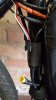
Please see attached the 3 pictures to help assess my problem!

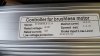
I have a kt controller 48v 40amp controller.

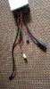
Firstly is the 3 wires (red white and black) jst connector the pedal assist cable? if so i have two possible options for connectivity.

Option 1
Make an adapter cable

Option 2
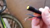
Take the controller apart an resolder the 3pin ip65 yellow warerproof connector direct to the circuit board. If so what wires need to be soldered to board?

Any help would be appreciated if someone has had the same issue!

Is there also a setting i need to enable on my lcd3 display to activate pedal assist as i have tried all combinations with the wires to initiate the motor when i rotate the pedal and all trials have failed so far in enabling the pedal assist!

cheers
phil

20170709_132951.jpg 20170709_133025.jpg pedal assist cable.jpg
 
Last edited:
D

Deleted member 4366

Guest
You need to show us a picture of the controller with all of its connectors laid out, so that we can see them clearly.
 

Slowplow

Finding my (electric) wheels
Apr 13, 2016
22
0
on a rock orbiting the sun
Many thanks for help d8veh!

As you can see i have:

1. a motor phase cable waterproof ip66 (i think)
2. System Cable waterproof ip65 (i think)
3. battery cables (red black xt60 connector)
4. unknown (guessing its the pas cable (pedal assist) black jst 3pin connector (wires red black white)

please find below a photo of the connectors20170709_154719 (002).jpg
 
D

Deleted member 4366

Guest
That type normally has a harness that runs up to the handlebars then splits into 4: 2x brakes, throttle and LCD, which means that that red/blck/white connector is either for PAS or a wheel-speed sensor. Out of the two, KT nearly always use red/black/white for the wheel-speed sensor, so that's what I'd bet on.

How many pins in that longest black one?
 

Slowplow

Finding my (electric) wheels
Apr 13, 2016
22
0
on a rock orbiting the sun
That type normally has a harness that runs up to the handlebars then splits into 4: 2x brakes, throttle and LCD, which means that that red/blck/white connector is either for PAS or a wheel-speed sensor. Out of the two, KT nearly always use red/black/white for the wheel-speed sensor, so that's what I'd bet on.
So if i want to make an adapter cable to enable pedal assist which cables do i connect? as they are different colours?

black jst cable is red/white black
The ip65 waterproof cable is red blue black. i have tried all combinations to try and get the pedal assist to initiate without success.

red to red
black to black
white to blue

no combination works

my only thought is i have to enable a setting on the lcd3 display?
 

anotherkiwi

Esteemed Pedelecer
Jan 26, 2015
7,845
5,786
The European Union
Red, white and black is speed sensor I think too. PAS usually has yellow, brown and black on KT.
 
D

Deleted member 4366

Guest
The ip65 waterproof cable is red blue black.
Is that the throttle connector then?

I don't understand: You keep mentioning settings in the LCD, but there is no LCD and no connector for it!
 

Slowplow

Finding my (electric) wheels
Apr 13, 2016
22
0
on a rock orbiting the sun
Is that the throttle connector then?

I don't understand: You keep mentioning settings in the LCD, but there is no LCD and no connector for it!
i have an lcd 3 display that connects via an ip65 green connector to the system cable.

my two brakes use 2 red ip 65 connectors via system cable

my throttle uses the yellow ip 65 connector via the system cable.

I was unsure if the lcd3 had an option in the advanced settings that enabled pedal assist? not sure?

so the only cable left to connect my pedal assist sensor is the red white black cable as shown above.

so im confused how to attach it?
 

rich_r

Pedelecer
Jun 23, 2017
89
32
50
North Yorkshire
P3 enables PAS, and C1 sets the type and number of magnets (usually 7 for 12 magnet, but for some reason mine needed C1=8).

However it seems odd that you have the coloured IP65 connectors for brake levers, throttle, display etc but not for the PAS sensor (usually a 15cm long cable with three pin yellow connector).
 

Slowplow

Finding my (electric) wheels
Apr 13, 2016
22
0
on a rock orbiting the sun
P3 enables PAS, and C1 sets the type and number of magnets (usually 7 for 12 magnet, but for some reason mine needed C1=8).

However it seems odd that you have the coloured IP65 connectors for brake levers, throttle, display etc but not for the PAS sensor (usually a 15cm long cable with three pin yellow connector).

many thanks richard i will see if i have pas enabled! and retest

yes i expected the yellow ip65 connector from the tk controller like my previous 28amp controller i think i will take both controllers appart and hopefully work out where the pas sensor cable connects within the unit.

will post pictures on how to sort if i ever get it working lol
 

Slowplow

Finding my (electric) wheels
Apr 13, 2016
22
0
on a rock orbiting the sun
Is that the throttle connector then?

I don't understand: You keep mentioning settings in the LCD, but there is no LCD and no connector for it!


28amp controller


28amp controller showing ip65 connection for pedal assist wires


will mimic this layout and resolder the ip65 cable direct to board hopefullly this will work!
 

Slowplow

Finding my (electric) wheels
Apr 13, 2016
22
0
on a rock orbiting the sun
P3 enables PAS, and C1 sets the type and number of magnets (usually 7 for 12 magnet, but for some reason mine needed C1=8).

However it seems odd that you have the coloured IP65 connectors for brake levers, throttle, display etc but not for the PAS sensor (usually a 15cm long cable with three pin yellow connector).

i have mixed kits

i originally purchased a greenedge ebike 36v system (novice error)
then upgraded it to cyclotricity 48v 1000w system with 28amp controller lcd1
then upgraded further to a wing controller 48v 40amp kt controller with lcd3 display

i modified my mech 160s disc brakes to hydraulic 180s and modified the wires to work with 2pin ip65 connectors (instead of the 3pin yellow type it came with) all works great.

but i have to say the darn pedal assist has had me puzzled but will tinker as its all fun!

Built my own battery from old laptop batteries all individually tested and classified by chemical types. all fused between series (13s 8p) battery is amazing i have doubled up balance leads to allow a pair of low voltage sensors to alarm me when at 15% or if i want to use my extra balancing units (hitex) really works well. Does 20 miles easy at 32mph. With 2 packs i have some amazing range.
 
Last edited:
D

Deleted member 4366

Guest
I haven't a clue what you have or what you're trying to achieve because the facts you wrote conflict with each other and you didn't answer my questions, but good luck with it.
 

Slowplow

Finding my (electric) wheels
Apr 13, 2016
22
0
on a rock orbiting the sun
I haven't a clue what you have or what you're trying to achieve because the facts you wrote conflict with each other and you didn't answer my questions, but good luck with it.

TY for you input anyway!

Its because my kit is a mixture of a few kits, i have tinkered abit and mixed and matched.

The lcd3 has an option apparently that enables pedal assist which i need to check if its enabled, i have just realised that my old pedal assist sensor only has 8 magnets and believe i need to purchase a wing bike pedal assist sensor that has more magnets which may be the issue.
 
D

Deleted member 4366

Guest
I asked you how many pins in the long black lead. You said three. Where's the connector for the LCD? The only other connectors are for the motor and battery. LCDs need a minimum of 5 pins.
 

Slowplow

Finding my (electric) wheels
Apr 13, 2016
22
0
on a rock orbiting the sun
That type normally has a harness that runs up to the handlebars then splits into 4: 2x brakes, throttle and LCD, which means that that red/blck/white connector is either for PAS or a wheel-speed sensor. Out of the two, KT nearly always use red/black/white for the wheel-speed sensor, so that's what I'd bet on.

How many pins in that longest black one?
sorry d8veh i didnt see your question earlier regarding system cable pins

20170709_205047.jpg

8 pins!
 
D

Deleted member 4366

Guest
OK, so you have the 4 into one harness that I mentioned in post #4.

Let's see if I understand you now. You want to unsolder your speed sensor and solder your PAS connector in its place? I wouldn't do that until youve tested what the connectors for:

Plug in your controller to your bike and switch it on. Set the LCD to level 1. Using a small screwdriver or other metal object, tap the pins so that you short the red to the white one. Tap at a frequency of about 2 taps per second. One of two things will happen: either you'll see a speed on the LCD or the back wheel will start to spin so make sure the wheel is off the ground. Maybe get a friend to help.

If it's the speed sensor, connecting your PAS there won't magically transform it. All you'll get is a high speed show on the LCD in proportion to how fast you pedal.

It would make more sense to solder the PAS sensor into the equivalent position to where it was on the old PCB, but I doubt that that will work because the chance of having equivalent software in the CPU is not high.
 

Slowplow

Finding my (electric) wheels
Apr 13, 2016
22
0
on a rock orbiting the sun
OK, so you have the 4 into one harness that I mentioned in post #4.

Let's see if I understand you now. You want to unsolder your speed sensor and solder your PAS connector in its place? I wouldn't do that until youve tested what the connectors for:

Plug in your controller to your bike and switch it on. Set the LCD to level 1. Using a small screwdriver or other metal object, tap the pins so that you short the red to the white one. Tap at a frequency of about 2 taps per second. One of two things will happen: either you'll see a speed on the LCD or the back wheel will start to spin so make sure the wheel is off the ground. Maybe get a friend to help.

If it's the speed sensor, connecting your PAS there won't magically transform it. All you'll get is a high speed show on the LCD in proportion to how fast you pedal.

It would make more sense to solder the PAS sensor into the equivalent position to where it was on the old PCB, but I doubt that that will work because the chance of having equivalent software in the CPU is not high.

many thanks d8veh!
Will try and have a look this week and report back here as i doubt i will be the only person to have this issue.
 
D

Deleted member 4366

Guest
Whenever you buy a controller, you have to check that it has the functions that you want. if it doesn't say PAS in the listing, you probably won't get it. the same with EABS, regen, lights and things like that.
 

Slowplow

Finding my (electric) wheels
Apr 13, 2016
22
0
on a rock orbiting the sun
OK, so you have the 4 into one harness that I mentioned in post #4.

Let's see if I understand you now. You want to unsolder your speed sensor and solder your PAS connector in its place? I wouldn't do that until youve tested what the connectors for:

Plug in your controller to your bike and switch it on. Set the LCD to level 1. Using a small screwdriver or other metal object, tap the pins so that you short the red to the white one. Tap at a frequency of about 2 taps per second. One of two things will happen: either you'll see a speed on the LCD or the back wheel will start to spin so make sure the wheel is off the ground. Maybe get a friend to help.

If it's the speed sensor, connecting your PAS there won't magically transform it. All you'll get is a high speed show on the LCD in proportion to how fast you pedal.

It would make more sense to solder the PAS sensor into the equivalent position to where it was on the old PCB, but I doubt that that will work because the chance of having equivalent software in the CPU is not high.

Hi d8veh,

i tried what you recommended!

The following combination span the wheel:-
black wire tapping white = wheel rotation & lcd displayed speed

black/white 4.9v
black/red 4.3v

i have enabled pasand set the lcd to be configured to 8 magnets and wired according to your recommendation but still hub does not rotate when i pedal?

very strange as it engages when i tap the wires together
 

Advertisers