
Here is a walkthrough on how to carry out the Cyclamatic controller mod.
Please excuse the poor quality pictures. I only had my 2MP phone to hand.
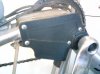
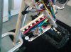
1) Here is where you access the compartment containing the controller. Undo the 4 screws and remove the plastic cover.
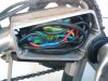
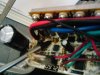
2) This is what it looks like with cover removed. Note the birdsnest of wiring stuffed in front of the controller.
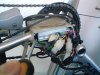
3) Carefully pull out the wiring and you will see the controller at the back of the compartment. It is fitted very snuggly in there!!
To remove the controller, I inserted a long flat headed screwdriver into the left hand side to lever on the side of the controller case, and at the same time gently tugged on the wiring on the right where it enters the controller. A kind of left/right, lever/tug motion will see the controller eventually sliding out.
Note: Be patient with this so as not to damage the wiring loom.
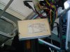
4) Here is the controller out of the compartment.
There are 3 crossheaded bolts on the side of the casing (not shown), which attach the heatsink and circuit board to the casing. Remove them.
Then remove the 4 small screws (not shown) at the end of the casing where the wiring exits the case.
5) Slide the circuit board out of the casing.
6) The shunt is a rectangular shaped wire which looks like a piece of metal coat hanger. It hides underneath the large black capacitor, opposite end of the wiring loom.
The capacitor can be gently lifted up to carry out the mod, then pushed back once you have carried out the procedure.
7) You will see that at both ends of the shunt, where they attach to the circuit board, there is some solder.
You are aiming to add some solder to either end to decrease the resistance of the shunt.
This effectively increases the amount of power that the motor can draw from the battery.
Don't over do it with the solder, or too many amps will be drawn from the battery and you will blow the 20amp fuse in the battery.
Just a little bit extra will see a nice extra bit of oomph, but don't be expecting to turn the Cyclamatic into a Wisper.
I won't detail putting it all back together, as it's just the reverse of taking it apart.
Happy modding
Please excuse the poor quality pictures. I only had my 2MP phone to hand.
1) Here is where you access the compartment containing the controller. Undo the 4 screws and remove the plastic cover.
2) This is what it looks like with cover removed. Note the birdsnest of wiring stuffed in front of the controller.
3) Carefully pull out the wiring and you will see the controller at the back of the compartment. It is fitted very snuggly in there!!
To remove the controller, I inserted a long flat headed screwdriver into the left hand side to lever on the side of the controller case, and at the same time gently tugged on the wiring on the right where it enters the controller. A kind of left/right, lever/tug motion will see the controller eventually sliding out.
Note: Be patient with this so as not to damage the wiring loom.
4) Here is the controller out of the compartment.
There are 3 crossheaded bolts on the side of the casing (not shown), which attach the heatsink and circuit board to the casing. Remove them.
Then remove the 4 small screws (not shown) at the end of the casing where the wiring exits the case.
5) Slide the circuit board out of the casing.
6) The shunt is a rectangular shaped wire which looks like a piece of metal coat hanger. It hides underneath the large black capacitor, opposite end of the wiring loom.
The capacitor can be gently lifted up to carry out the mod, then pushed back once you have carried out the procedure.
7) You will see that at both ends of the shunt, where they attach to the circuit board, there is some solder.
You are aiming to add some solder to either end to decrease the resistance of the shunt.
This effectively increases the amount of power that the motor can draw from the battery.
Don't over do it with the solder, or too many amps will be drawn from the battery and you will blow the 20amp fuse in the battery.
Just a little bit extra will see a nice extra bit of oomph, but don't be expecting to turn the Cyclamatic into a Wisper.
I won't detail putting it all back together, as it's just the reverse of taking it apart.
Happy modding
Last edited: