What is the consumption of each motor wire?

joaquín

Finding my (electric) wheels
Dec 14, 2015
14
1
35
Hi, I´m building a case for my battery, and now I´m choosing the connectors so I don´t have to send the wires into the case.

My bike has a 250W geared motor with torque sensor.

For the signal cables is ok, there is full of connectors for that.

But, what about the motor wires? It has 5 wires for signal and three for power, this three power wires that goes to the inductions, what would be the maximum Amps it would consum?

At the controller this wire says 1,5mm2, I have cheked out, and it means the wire can resist a maximum of arround 5 amps each, is it ok?

Regards!
 

Danidl

Esteemed Pedelecer
Sep 29, 2016
8,611
12,256
73
Ireland
Hi, I´m building a case for my battery, and now I´m choosing the connectors so I don´t have to send the wires into the case.

My bike has a 250W geared motor with torque sensor.

For the signal cables is ok, there is full of connectors for that.

But, what about the motor wires? It has 5 wires for signal and three for power, this three power wires that goes to the inductions, what would be the maximum Amps it would consum?

At the controller this wire says 1,5mm2, I have cheked out, and it means the wire can resist a maximum of arround 5 amps each, is it ok?

Regards!
It does to a minor extent depend on the voltage supply from the battery. The three thick wires are part of what is called a three phase supply and each of these leads in turn acts as a source and a return for current . For a 36v battery driving a 250w load the total average current is about 7amp, shared between these leads. The average current in any lead is this divided by 1.73 or 4 amps.
If the motor were stalled or running inefficiently the current will be much higher, but that will not be a problem in the powerleads...... although it could be in the motor windings.
Excess current causes temperature rise. The temperature of the insulation would need to rise to maybe 150 degree Celsius to melt it and then much higher if it were to melt the copper in the cable itself up to 1000

The guidelines you are referring to of 5 amps refer to cable use in domestic settings where it might be installed behind insulating panels with minimal airflow
 
D

Deleted member 4366

Guest
You could say that the maximum current taken from the battery is divided by three, so if you have a 15 amp controller, there's an average of 5 amps in each phase wire; however, the current isn't continuous. It goes in very short pulses, so instantaneous current can be very high, which is why you have a big capacitor over the battery wires. I guess that for wire rating, you can use the average current of 5 amps max.

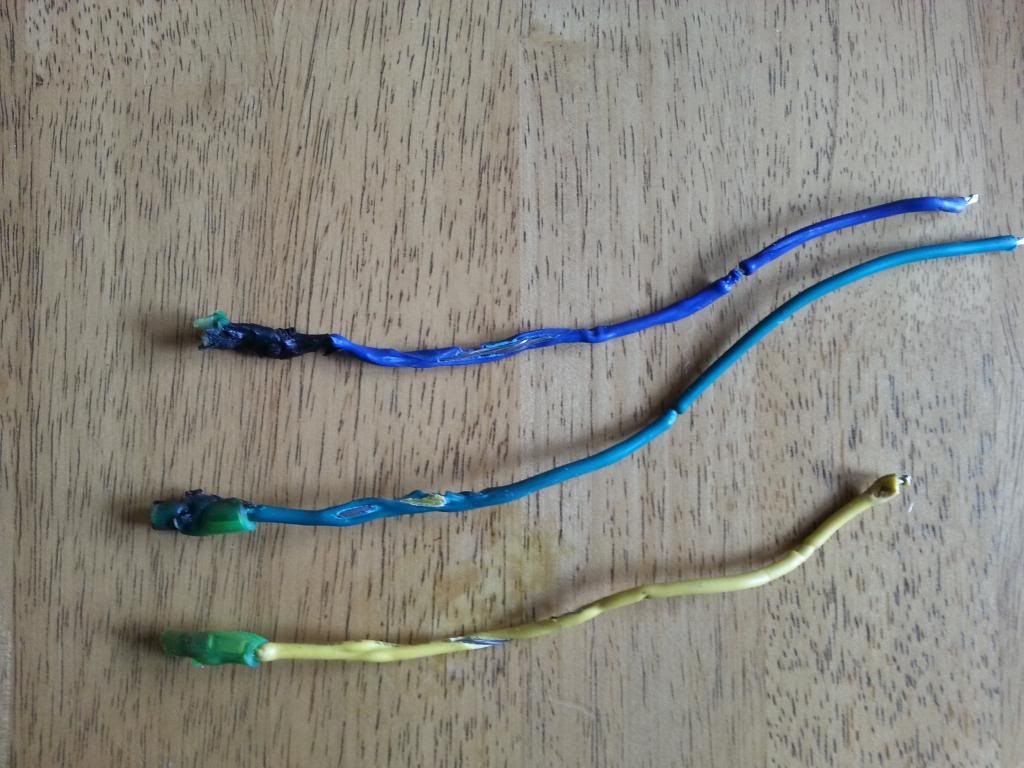
It's best to use PTFE coated wire, which has high heat resistance. I've seen controller wires melt before. These went at 30 amps from the battery:

 
  • Like
Reactions: Danidl

Advertisers