Voltage converters - Checking quality / spec & connecting

103Alex1

Esteemed Pedelecer
Sep 29, 2012
2,228
67
Received the last of my outstanding voltage converters today and would appreciate some help with checking whether they're the right spec and also how to wire up in the case of one of them.

This is the array ... they're all HRD converters rated to 3A with the exception of the one at the right of this photo which is an LM2956HV adjustable converter with 2 heatsinks - also rated to 3A. Interesting how big the heatsinks and copper wounds are on the HRD ones compared to the LM2956HV one :eek: !


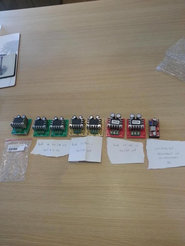
First, connecting up - I'm fine on the LM2956HV as it's clearly marked. Just to be double sure, on the others, except the red ones, there are 4 screw terminals :


I am guessing that going from bottom screw to top on the above photo, the wires go in the green screw terminals in the following order :

Bottom screw - battery positive
Next up - battery 0V
Next up - device 0V
Top screw - device positive feed

Is that right ?

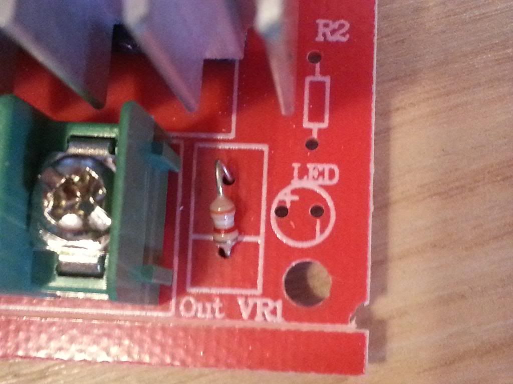
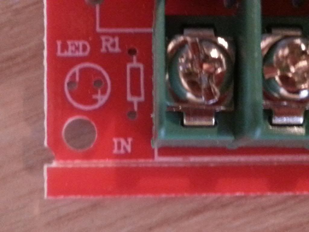
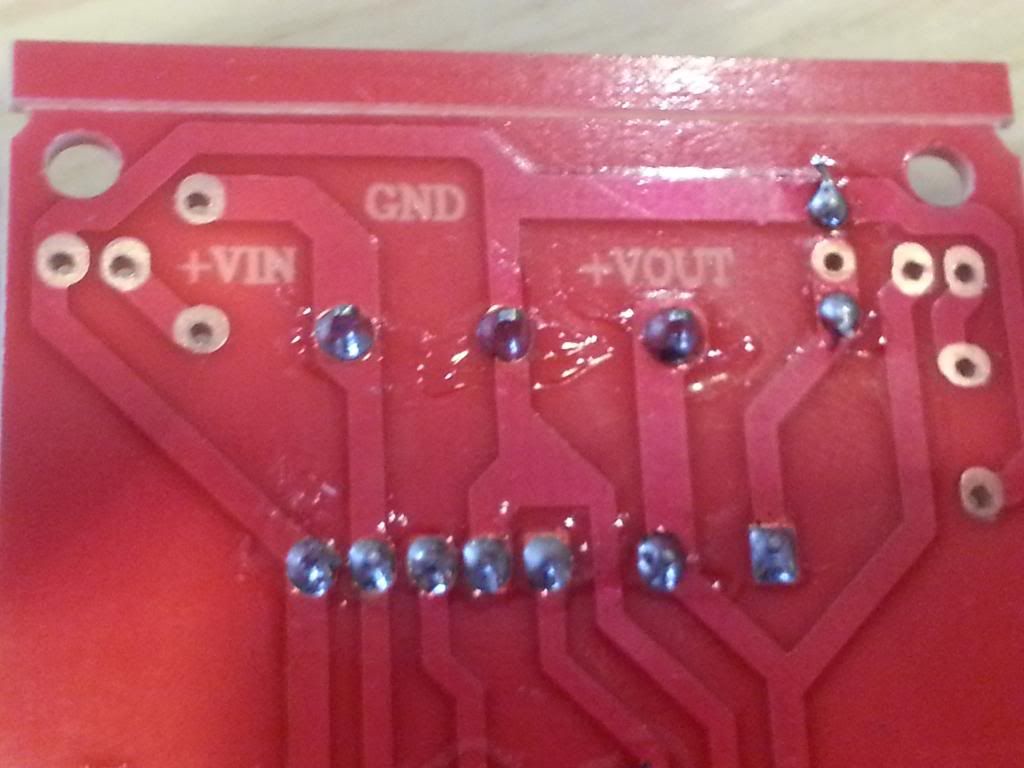
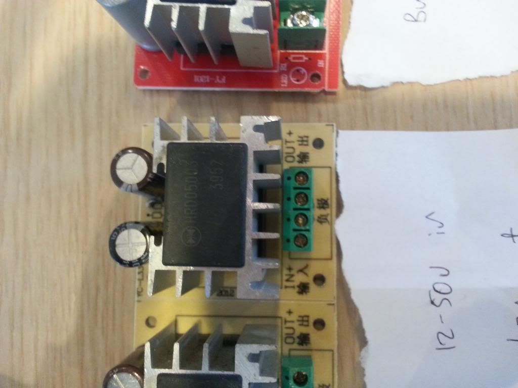
The red ones are slightly different - there are only 3 screw terminals and what looks like a tiny resistor is soldered onto the board marked 'Out VR1". This is a close-up - sorry a bit out of focus (shaky hands !) :


Any ideas how this is connected ?
 
Last edited:

103Alex1

Esteemed Pedelecer
Sep 29, 2012
2,228
67
Checking components used

Sorry - a bit tekkie all this, but also wanted to check the components used on the HRD devices as a couple came from Shenzen and just thought prudent to check the components first before hooking up my stuff.

They are all variable input / fixed output converters. There's a mix of 3 output ratings - 5V, 9V and 12V.

The black chip over the top is as follows :

5V - HRD05003E
9V - HRD05003
12V - HRD12003

The 9V has an additional resistor adjacent to the brown capacitor which the 5V doesn't have.

The capacitors are as follows :

5V - Black - 150uF 63V ZHN CD112A (M) 105 degrees C / Brown - 16V (M) 105 degrees C

9V - Black - 150uF 63V ZHN CD112A (M) 105 degrees C / Brown - 16V (M) 105 degrees C

12V - Black - 150uF 63V ZHN CD112A (M) 105 degrees C / Brown - 16V (M) 105 degrees C

9V RED - 2 silver capacitors, larger in size than those on the other HRDs, one marked 50V / 105 degrees C HD, and the other marked 25V / 105 degrees C FC.

Do those capacitors look right /adequate for the converters they're being used on (I'm feeding them off a 36V battery so input voltage could be anything up to 42V I guess depending on state of battery charge ?).

As far as testing output voltage is concerned I guess the way is screw in a supply and test the 'outs'. The wisdom of the wise ones would be welcomed :)
 
D

Deleted member 4366

Guest
The 4 pin ones look a bit more straight-forward as they're marked in and out. My guess is that the two 0Vs go to the middle two pins. You can check with your meter on bleep. they're probably connected. Check the other ones too because if they all bleep, you haven't proved anything. Looking at the 4 pin one again, they have a common symbol - the darker one - that is probably 0V, so 0V might be bottom and 3rd pins. Your meter should confirm.

The three pin ones are a bit harder. I would guess that the middle pin is a common 0V with the in and out on the outsides. I can see a marking near the top that says V something and is that "in" and "out" in small writing?.What's the marking on the other side? If the something is a Chinese symbol, compare it to the 4 pin one to see if you can match the symbols for in and out.

Another way to check is to join the wires and switch on. If the capacitor cases shoot off like bullets after a couple of seconds with lots of smoke and a nasty smell. then you wired it up the wrong way. Make sure that the capacitors aren't pointing at anything delicate - like you - because it'll 'kin hurt.

The rating of the caps is the maximum before they pop, As you're well below that, you;ll be OK.

They pop when you connect reverse polarity or when you exceed the maximum voltage by more than about 10%.
 
Last edited by a moderator:

103Alex1

Esteemed Pedelecer
Sep 29, 2012
2,228
67
OK - you're absolutely right on the 4-screw ones. Can actually see by just turning over - which I completely forgot to look at ...


The left hand solder points correspond to the screw terminals and the middle 2 are joined, but untraced so must therefore be the 0V input and outputs. The +ve sides are marked on the front - so all good.

On the red, here's a close-up of the front of the board :


... and here's the reverse with markings


The middle is therefore a common 0V in / out as you suspected.

What's quite interesting though are the contact points marked LED on the front which you can see on the reverse ... wonder what the purpose of those options are ?
 
Last edited:

Old_Dave

Esteemed Pedelecer
Sep 15, 2012
1,211
2
Dumfries & Galloway
The space for the led and it's associated current limiting resistor are there to show that power is reaching the device..


Sent from my iPhone using Tapatalk
 

Scimitar

Esteemed Pedelecer
Jul 31, 2010
1,772
40
Ireland
Yes, it's common enough on production PCBs to have 'phantom' component places, where they've been used in pre-production or design boards, but are left out for cheaper production ones. Occasionally the blank spaces will be filled for a more versatile model.
 

103Alex1

Esteemed Pedelecer
Sep 29, 2012
2,228
67
Thanks - that makes sense.

Any rule of thumb on the capacitor ratings that should be used on these things and the split between the first and the 2nd ? The 2 9V types have very different capacitor modules.
 

Old_Dave

Esteemed Pedelecer
Sep 15, 2012
1,211
2
Dumfries & Galloway
Any rule of thumb on the capacitor ratings
As d8veh said above.. 10% above the actual voltage is a 1/2 decent rule, but some times its cheaper (cos of preferred values and where your buying from) to go above that.

As an aside... 63v can sometimes be cheaper than 50v for the same size
 

103Alex1

Esteemed Pedelecer
Sep 29, 2012
2,228
67
As d8veh said above.. 10% above the actual voltage is a 1/2 decent rule, but some times its cheaper (cos of preferred values and where your buying from) to go above that.

As an aside... 63v can sometimes be cheaper than 50v for the same size
Ah - thanks. Didn't spot the edit above with the capacitor info. Just spotted on the trace that the higher rated capacitor is on the V IN trace and the smaller one is on the V OUT trace - so that's whey there are 2 :).
 

103Alex1

Esteemed Pedelecer
Sep 29, 2012
2,228
67
Connected up all these HRD converters and they all seem pretty close to the rated output voltage, which bodes well :). Was expecting at least one 'dud' as most of them were pretty inexpensive.

Readings obtained as follows :

E-bay Supplier - MarcMart - 5v - Rated 5V / Read output - 5.11V Price £2.99 ea

E-bay Supplier - Kuyaya520 - 9v (Red boards) - Rated 9V / Read outputs 9.19V & 9.24V - Price $2.99 ea (and 7 weeks' wait !)

E-bay Supplier - tchwarehouse - 9v (Yellow boards) - Rated 9V / Read outputs 9.23V & 9.24V - Price $5.68 ea

E-bay Supplier - tchwarehouse - 12v (Yellow boards) - Rated 12V / Read outputs 12.20V & 12.20V - Price $6.68 ea

These HRD converters are a lot cheaper than the adjustable LM2596HV converters that are also rated 3A, and not so compact, but as the adjustable ones are $13.50 each with postage, if you only need a fixed output voltage they do make sense cost-wise - especially if you need a few. Impossible to say on component quality - the OKI adjustable converters do look like they're not made from recycled components ! But everything at a price.
 
D

Deleted member 4366

Guest
Don't forget that your voltmeter might not be accurate. All the readings are high by the same amount approximately. That might tell you something!
 

103Alex1

Esteemed Pedelecer
Sep 29, 2012
2,228
67
I think you may be on to something there ! :)