Help! Tongsheng thumb throttle

Pumpalump

Finding my (electric) wheels
Nov 22, 2020
21
4
Hi all,
Totally confused about adding a thumb throttle to my bike.
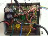
I have seen various comment about this, I have a TSDZ2 motor, the cable coming out of the motor ie controller has six pins, I have a VLCD5 display, 48V Battery and 500w motor.
Question: Will a thumb throttle work by just plugging it into the middle socket at the back of the display?
If not what do I need to do to make it work.
Thanks in advance.
Phil
 

harrys

Esteemed Pedelecer
Dec 1, 2016
333
89
73
Chicago, USA
As I understand it, the 6 pin and 8 pin controller circuit boards are the same, but the display cable doesn't contain the +5 throttle power and throttle signal. If you plug a throttle into the middle of your 6 pin VLDC5, it's not connected. You need a VLDC5 with an 8 pin cable and an 8 pin controller cable. I believe some people have wired the 8 pin cable into the controller.

If you go to this link, they show the board positions for the throttle signal, power and ground on a controller. You should read it first, but here's the picture of the controller showing where the 8 pin cable would attach the extra wires for the throttle.
.
TSDZ2_motor_controller_without_throttle_wires.jpeg

I would presume you need an 8 pin VLDC5 and a matching 8 pin cable. Hopefully, it's off a dead TSDZ2 controller, so the wire colors match. You reconnect the six orignal wires and add the two new ones to THR amd +5V anove, Ugh. That's a lot of work eith high potential for error.

If you must have a throttle, here's my proposal, as yet untested. Instead of routing the signals thru the display, connect the throttle, any throttle, directly to the controller using the THR, +5, and GND positions shown in the picture. Your old VLDC5 will work, etc.

However, there are different controller versions, and the connector positions can change. I wouldn't try it unless my controller matched the above picture exactly.
 
  • Like
Reactions: Pumpalump

Nealh

Esteemed Pedelecer
Aug 7, 2014
20,764
8,443
61
West Sx RH
In the UK it would make it a twist and go and not pedal first so illegal by law.

UK has a few legal options.
For non twist and go one needs a KT set up to pedal first.
By a Wisper bike that conforms to twist & go via a V5.
Take your bike to a test station and have it tested so that it conforms .
 
  • Like
Reactions: Pumpalump

Pumpalump

Finding my (electric) wheels
Nov 22, 2020
21
4
As I understand it, the 6 pin and 8 pin controller circuit boards are the same, but the display cable doesn't contain the +5 throttle power and throttle signal. If you plug a throttle into the middle of your 6 pin VLDC5, it's not connected. You need a VLDC5 with an 8 pin cable and an 8 pin controller cable. I believe some people have wired the 8 pin cable into the controller.

If you go to this link, they show the board positions for the throttle signal, power and ground on a controller. You should read it first, but here's the picture of the controller showing where the 8 pin cable would attach the extra wires for the throttle.
.
View attachment 59509

I would presume you need an 8 pin VLDC5 and a matching 8 pin cable. Hopefully, it's off a dead TSDZ2 controller, so the wire colors match. You reconnect the six orignal wires and add the two new ones to THR amd +5V anove, Ugh. That's a lot of work eith high potential for error.

If you must have a throttle, here's my proposal, as yet untested. Instead of routing the signals thru the display, connect the throttle, any throttle, directly to the controller using the THR, +5, and GND positions shown in the picture. Your old VLDC5 will work, etc.

However, there are different controller versions, and the connector positions can change. I wouldn't try it unless my controller matched the above picture exactly.
Thanks for the response, think I understand now.
I think the easiest option would be to hot wire the throttle direct into the control circuit board.
From memory I think I would only need to remove one cover from the motor.
 

Pumpalump

Finding my (electric) wheels
Nov 22, 2020
21
4
In the UK it would make it a twist and go and not pedal first so illegal by law.

UK has a few legal options.
For non twist and go one needs a KT set up to pedal first.
By a Wisper bike that conforms to twist & go via a V5.
Take your bike to a test station and have it tested so that it conforms .
Its ok as I only ride mine of road on private land however I see lots of Delveroo bikes bombing around when im in my car at speeds well over the 15mph limit where I live and the riders dont even touch the pedals but nobody is policing them. No lights, go through red lights etc. One rule for one................
 

Pumpalump

Finding my (electric) wheels
Nov 22, 2020
21
4
As I understand it, the 6 pin and 8 pin controller circuit boards are the same, but the display cable doesn't contain the +5 throttle power and throttle signal. If you plug a throttle into the middle of your 6 pin VLDC5, it's not connected. You need a VLDC5 with an 8 pin cable and an 8 pin controller cable. I believe some people have wired the 8 pin cable into the controller.

If you go to this link, they show the board positions for the throttle signal, power and ground on a controller. You should read it first, but here's the picture of the controller showing where the 8 pin cable would attach the extra wires for the throttle.
.
View attachment 59509

I would presume you need an 8 pin VLDC5 and a matching 8 pin cable. Hopefully, it's off a dead TSDZ2 controller, so the wire colors match. You reconnect the six orignal wires and add the two new ones to THR amd +5V anove, Ugh. That's a lot of work eith high potential for error.

If you must have a throttle, here's my proposal, as yet untested. Instead of routing the signals thru the display, connect the throttle, any throttle, directly to the controller using the THR, +5, and GND positions shown in the picture. Your old VLDC5 will work, etc.

However, there are different controller versions, and the connector positions can change. I wouldn't try it unless my controller matched the above picture exactly.
Hi,
From memory when I had to replace a control board I it was is sealed with a layer of resin so not sure how soldering the wires in would be possible, I could try grinding the resin down with a dremell I guess until I get to the connections ?