Pedal sensor spoof

saneagle

Esteemed Pedelecer
Oct 10, 2010
8,283
3,778
Telford
I bought some of these from Ebay for £1.40 each - low frequency option:

I figured out that the average person pedals at about 60 rpm = 1 turn per second. A good pedal sensor has 12 magnets, so makes 12 pulses per rotation = 12 pulses/second or 12 Hz. I don't think the pulse frequency matters that much because the motor still kicks in when you're pedallin slowly, and still works when you go nuts. so anything between about 5 hz and 30hz should work.

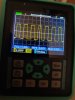
I have a pocket oscilloscope, so I can set the device exactly at 12 hz, but I'm pretty sure that you could get it working by trial error - just turn the screw adjuster up and down until it works. Tomorrow, I'll check the next ones to see what the default setting is and figure out which way to turn the screw and how much to get approx 12hz.

You can see that it makes a nice clean square wave, just like the pedal sensor:
62830

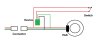
I'll test it on a bike tomorrow. The plan is to splice it in to the pedal sensor connector and put a switch on it so that I can work the motor from a switch without pedalling.

62831
 
Last edited:

Benjahmin

Esteemed Pedelecer
Nov 10, 2014
2,651
1,776
70
West Wales
It'll be interesting to see what the 'switch' is. Obviously a physical switch would be illegal .
I suggest an iris scanner which will operate the device for a programmed time when you look directly at it:cool:. Just be careful where you look when you are pulled over.
 

thelarkbox

Esteemed Pedelecer
Aug 23, 2023
1,520
476
oxon
Put a lil coil into the wire ends you would normally terminate with a switch perhaps, and then if secured at the saddle rim perpendicular to the frame each wire opposite the other with a bit of exposed core on each end circa 1 cm apart.

Then when sat on the saddle simply clench to speed up relax to slow down.

Adjust the distance between exposed wire ends to suit your arse/clench capacity.
 

guerney

Esteemed Pedelecer
Sep 7, 2021
11,901
3,348
Would two isolated contacts next to each hangrip bridged by two thumbs (attached to the same human body) be regarded as a physical switch? According to my measurements, with 5V input, about 30mV to 40mV gets through to the other thumb.
 

saneagle

Esteemed Pedelecer
Oct 10, 2010
8,283
3,778
Telford
Good suggestions, but here we go:
I'm using a reed switch on the handlebar. If you butt it up against anything like the PAS buttons brake or anything like that, it looks like it's the wire for it.
62848

62849

62850
 
  • Like
Reactions: Woosh

saneagle

Esteemed Pedelecer
Oct 10, 2010
8,283
3,778
Telford
To install it, just pull the pedal sensor apart and connect each side.

This is what I found from testing. It worked straight away, and so did the pedal assist when I tried it, then it stopped working. I disconnected the pedal sensor, and it worked perfectly again. The idea is that it's an either-or system - PAS or thumb, but it can't quite work like that at the moment. The device is pulsing properly, but if the pedal stops with a pedal sensor magnet over the hall sensor, it either holds the shared signal at 5v or shorts it to ground. I'm not sure which. I'll have to check. This pedal sensor signal therefore over-rides the one from the device. I think it works if you can hold the pedal in a position where a magnet isn't over the sensor, but that's not easy when you're riding the bike because you'd need to hold it to within a 24th of a turn.

In summary, it works perfectly as a stealth throttle to replace the PAS, but I need to find a way to separate the signals. I can do it with a two-position switch, but I'd like it to work automatically. Can anyone think of a solution? I think it can be done with a transister and a couple of resistors, but I was hoping for something simpler.
 
Last edited:

Sparksandbangs

Pedelecer
Jan 16, 2025
53
16
To install it, just pull the pedal sensor apart and connect each side.

This is what I found from testing. It worked straight away, and so did the pedal assist when I tried it, then it stopped working. I disconnected the pedal sensor, and it worked perfectly again. The idea is that it's an either-or system - PAS or thumb, but it can't quite work like that at the moment. The device is pulsing properly, but if the pedal stops with a pedal sensor magnet over the hall sensor, it either holds the shared signal at 5v or shorts it to ground. I'm not sure which. I'll have to check. This pedal sensor signal therefore over-rides the one from the device. I think it works if you can hold the pedal in a position where a magnet isn't over the sensor, but that's not easy when you're riding the bike because you'd need to hold it to within a 24th of a turn.

In summary, it works perfectly as a stealth throttle to replace the PAS, but I need to find a way to separate the signals. I can do it with a two-position switch, but I'd like it to work automatically. Can anyone think of a solution?
Single pole double throw reed switch. Cuts the power to either the device or the pedal sensor.


saneagle

Esteemed Pedelecer
Oct 10, 2010
8,283
3,778
Telford

Sparksandbangs

Pedelecer
Jan 16, 2025
53
16
I can't help feeling it would be better to switch the signal rather than the power to make sure it is an instant cut over. Interesting to see what happens.
 

saneagle

Esteemed Pedelecer
Oct 10, 2010
8,283
3,778
Telford
I can't help feeling it would be better to switch the signal rather than the power to make sure it is an instant cut over. Interesting to see what happens.
I think you're right, but I'm hoping the changeover time should be short enough not to be a problem.
 

saneagle

Esteemed Pedelecer
Oct 10, 2010
8,283
3,778
Telford
Project is now complete and fully working. The pedal assist works as normal, and when you bring the magnet to the reed switch, the device provides the PAS signal, so the bike goes without pedalling until you take the magnet away, then it reverts back to normal PAS operation. You can stick the magnet in the finger or thumb of a glove, or use one of those fake thumbs I showed above (link below). I Used the NO/NC reed switch that Sparksandbangs linked above. I rewired it to do the switching on the signal wire, as suggested by Sparksandbangs because it still wouldn't work when switching the 5v. Here's the new schematic. I put two connectors on it so that I can simply unplug the PAS and plug in the device between them, so that I can uninstall it back to how it was before and/or put it on another bike, but if you want to install it permanently on your own bike, you can just splice it in to your PAS cable without connectors:

62865

 
Last edited:
  • Like
  • Useful
Reactions: Nealh and Bikes4two

guerney

Esteemed Pedelecer
Sep 7, 2021
11,901
3,348
If dudes wanted to press buttons instead: two momentary horn-type push switches under each thumb wired in series on the handlebar - if a cop presses one button to test for a throttle, nothing happens.


Without a throttle lever: If there an easy way to make a small circuit which automatically and gradually increases voltage to the throttle, which could be activated by two buttons wired in series, the cops wouldn't be able to activate it using one button.
 

Sparksandbangs

Pedelecer
Jan 16, 2025
53
16
If dudes wanted to press buttons instead: two momentary horn-type push switches under each thumb wired in series on the handlebar - if a cop presses one button to test for a throttle, nothing happens.


Without a throttle lever: If there an easy way to make a small circuit which automatically and gradually increases voltage to the throttle, which could be activated by two buttons wired in series, the cops wouldn't be able to activate it using one button.
There is the worry that they might work it out. I would suggest a third button in the middle of the handlebars to be activated by pressing with the nose.
 

guerney

Esteemed Pedelecer
Sep 7, 2021
11,901
3,348
There is the worry that they might work it out. I would suggest a third button in the middle of the handlebars to be activated by pressing with the nose.
A fourth button in series under the saddle cover, so the throttle only works when the rider is seated and two buttons either side are pressed, after arming the system with the noseprint reader in the middle. No two noses are exactly the same. It's impossible for the cop to have the same nose, without a plaster casting kit and quick setting silicone.


Put a lil coil into the wire ends you would normally terminate with a switch perhaps, and then if secured at the saddle rim perpendicular to the frame each wire opposite the other with a bit of exposed core on each end circa 1 cm apart.

Then when sat on the saddle simply clench to speed up relax to slow down.

Adjust the distance between exposed wire ends to suit your arse/clench capacity.
This should be combined with the two button either side and nose/noseprint button circuit suggested above, with butt recognition (no two butts are exactly the same) to prevent the bike accelerating when butts clench at the sight of cops.
 
Last edited:

Woosh

Trade Member
May 19, 2012
21,020
17,169
Southend on Sea
wooshbikes.co.uk
In summary, it works perfectly as a stealth throttle to replace the PAS, but I need to find a way to separate the signals. I can do it with a two-position switch, but I'd like it to work automatically. Can anyone think of a solution? I think it can be done with a transister and a couple of resistors, but I was hoping for something simpler.
How about prioritising pedalling (A) over manual triggering (B)?
I ask Grok and ChatGPT to design it in CMOS with minimum chip count. Both come up with essentially the same wiring diagram with just one CD4011 (Quad 2-input NOR gate, 14-pin DIP).
Do you want a schematic diagram?

:
 

saneagle

Esteemed Pedelecer
Oct 10, 2010
8,283
3,778
Telford
How about prioritising pedalling (A) over manual triggering (B)?
I ask Grok and ChatGPT to design it in CMOS with minimum chip count. Both come up with essentially the same wiring diagram with just one CD4011 (Quad 2-input NOR gate, 14-pin DIP).
Do you want a schematic diagram?

:
It's working perfectly now with the NO/NC reed switch and the schematic I showed in my last post. Just the device, the switch and the wires is all that's needed, but thanks anyway.

You could use the same switch method to have a throttle that's both limited to 6km/hr through a potentiometer and unlimited with the magnet.

In case anybody gets the wrong idea, I'm not suggesting anybody should do this. It's just an academic exercise to see how it could be done if the law changes. You need to keep your bike legal
 

Nealh

Esteemed Pedelecer
Aug 7, 2014
21,371
8,737
61
West Sx RH
A question to ask @d8veh , does one stiil get the five power levels with the KT using the spoof switch ?

My logic say's it will but can you confirm pls.
 

saneagle

Esteemed Pedelecer
Oct 10, 2010
8,283
3,778
Telford
A question to ask @d8veh , does one stiil get the five power levels with the KT using the spoof switch ?

My logic say's it will but can you confirm pls.
Yes. All it does is give the pedal sensor signal as if you're pedalling. The controller can't see the difference. It'll work on any bike with a cadence sensor, and it should enable one to fit a throttle to the carrera bikes with the 4 wire torque sensors.