Matching Peripherals with Controllers

Smoother

Just Joined
Aug 1, 2024
3
0
Ok, so I have a lil budding ebike/etrike business here in Central Florida USA and I'll be the 1st to admit that I don't know everything and am always up for learning more.
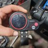
Having said that, I never trash anything that I can reuse elsewhere, but when it comes to Display/Switch/Throttle peripherals like this one that has 7 wires, is it possible to make it work with a controller that had a Voltage Display Gauge/Switch/Throttle requiring only a 5 wire connection?59140
 

saneagle

Esteemed Pedelecer
Oct 10, 2010
6,785
3,132
Telford
I'm not sure about this. I'm just using logic. It has the 5 normal wires that any LCD has: red battery voltage, blue switched battery voltage to power the controller, black ground and two data wires Rx and Tx. That means it works the same as as any normal LCD, except ut has a throttle. The throttle signal must be sent as data, not analogue, in which case logic says that it needs a special controller to interpret the throttle data. I've seen two versions of that device for which the two extra wires have different purposes. One has orange and red wires for a key-switch, in which case I think the blue wire must be orange; the other has purple and white wires for the lights.

If you fit it to the correct controller, you can't connect an independent throttle. If you connect it to a standard controller, you can use a standard throttle on the independent throttle connector, but there doesn't seem much point in that, when all you get from it is speed and battery display.
 
  • Like
Reactions: Smoother

Smoother

Just Joined
Aug 1, 2024
3
0
Just going by model numbers(WXGN), I would assume that these two go together. Unfortunately, whoever had this controller previously didn't retain the lil collars that explain the wires' usage, nor the connectors, and for whatever reason removed and didn't replace the MOSFET case screws. I did find, during a Google search, what appears to be an almost identical match of the controller/peripheral in question. The image shows the LCD to be a 4 wire connector and the throttle is a 3 wire connector....well, the peripheral appears to have once been a 7 wire waterproof connector that no longer has it's connector. Guess I'm gonna try to connect the 4 LCD and 3 Throttle wires to the 7 needed on the peripheral and see if that works?!?
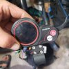
Image 1 = Peripheral and bare wires
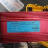
Image 2 = Controller
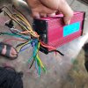
Image 3 = Controller's Clusterf**k of wires
Image 4 = Google search result image
Image 5 = That image's wiring explanation
5914259143591445914659147
 

Attachments

saneagle

Esteemed Pedelecer
Oct 10, 2010
6,785
3,132
Telford
Everything is there that you need. On connector 12, the normally red wire is orange, and the orange Next to it is the normally blue. The rest is straight forward. If there's doubt about which are the hall wires, you can open the controller and see them marked on the pcb: h1, h2 and h3 or uh, vh and wh or something like that. The black ground and red 5v are often soldered in the same line of 5. You don't need most of the other stuff, except you should do the self-recognition procedure if you fit a different motor, and make sure connector 11 wires are bridged.
 

Ghost1951

Esteemed Pedelecer
Jun 2, 2024
1,548
597
Everything is there that you need. On connector 12, the normally red wire is orange, and the orange Next to it is the normally blue. The rest is straight forward. If there's doubt about which are the hall wires, you can open the controller and see them marked on the pcb: h1, h2 and h3 or uh, vh and wh or something like that. The black ground and red 5v are often soldered in the same line of 5. You don't need most of the other stuff, except you should do the self-recognition procedure if you fit a different motor, and make sure connector 11 wires are bridged.
This kind of info given freely is a huge benefit to people.
 

Smoother

Just Joined
Aug 1, 2024
3
0
Ok, so my only question really is the motor I'm connecting it all to has 5 Halls and the white Hall sensor wire which I'm gonna go out on a limb and assume that it connects to the white wire that runs to the peripheral and gives it speed readout, etc. Right? Because the peripheral has 7 wires, the LCD connector has 4 from the controller and the throttle has 3 from the controller but I don't need 2 black grounds so that's 6 wires and then using the white hall sensor wire from the motor would make 7....sound right?
 

saneagle

Esteemed Pedelecer
Oct 10, 2010
6,785
3,132
Telford
The motor has 3 position sensing halls (blue, green and yellow) and one more pulsing one for the speed (white). The red and black provide the 5v for them.

The LCD needs a minimum of 5 wires (2 power, 2 coms and one switched power for the controller).

If you have 7 conductors in the main harness, they're the 5 for the LCD, one for the throttle signal and one for the the 5v. In that case the brakes must be separate. Normally, there's 8 wires to include one for the brakes.

The wires that run to your LCD are nothing to do with the motor.

The wiring diagram for your controller doesn't show a connection for a motor speed sensor. It must therefore be designed to work with a direct drive motor and it gets its speed from the commutation pulses.
 
Last edited: