Kalkhoff Battery: Connections & Voltage during charging

10mph

Esteemed Pedelecer
Dec 13, 2010
351
0
England
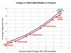
In a previous post, I summarised my measurements of the watts taken from the mains by the charger for my 18Ah Kalkhoff battery. I have now measured the voltage during charging with a newly aquired digital voltmeter but before reporting that I consider the battery connections:

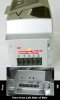
Connections view showing bottom of battery positioned ready to insert into the battery socket on my Agattu.


I have number the pins/sockets starting from pin 1 at the fore end of the bike.

When I took the voltage reading the battery had been discharged to the point when only 1 LED out of 5 was illuminated on the battery.

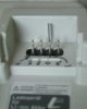
I confirmed that pins 1 and 4 were supplying the current for the bike's motor by observing that 462 ma flowed when I connected a 54 ohm resistor between pins 1 and 4.

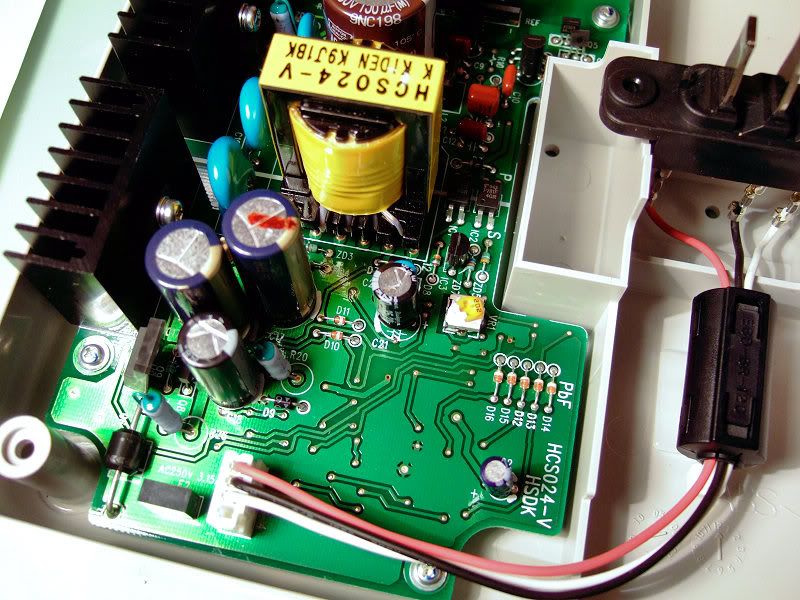
Here is the view of the battery charger pins in the same orientation/numbering system:


The charging power appears between pin 2 and pin 4. Pin 4 is +ve. However the charger is actually marked with the opposite polarity i.e. pin2 has a + and pin 4 has a - embossed on the plastic. I have marked the location of these embossed symbols in the picture above.. I don't know the reason for this marking which is the reverse of what I actually measure with a meter.
 

Attachments

Last edited:

10mph

Esteemed Pedelecer
Dec 13, 2010
351
0
England
Voltage during Charging

To measure voltage during charging I wrapped thin wires around pin 2 and pin 4 of the charger and then plugged the battery in.

The following graph shows how the voltage increases with time after the start of the charge.


It will be noted that the starting voltage was 25.6V, whereas when not connected to the charger the voltage was 25.4v. From this we see that the effective internal resistance during charging is 0.2V / 1.8A = approx 0.1 Ohm. ( 1.8A is the nominal charger current. I have not yet confirmed this by direct measurement since I will have to make a special connector in order to be able make a break between the charger and the battery for a current measurement.)

The charger switches off at 29.4V. Assuming that there are 7 cells in series inside the battery, this corresponds to 4.2V per cell. 4.2V is the maximum normally recommended for Li-ion chemistry.

After the charger switched off, the battery voltage gradually reduced by 0.2V to 29.2V
over a few minutes.

I shall have to do further tests to explore the lowest voltage region of the battery in the region where the low voltage cutoff operates. The no charge voltage at the point I had started charging with 1 LED lit had been 25.4V. This corresponds to 3.6V per cell.

I think that the shape of the curve is slightly different from that given in the Kalkhoff Agattu manual so that may be a somewhat idealised shape rather than actual measured values.
 

Attachments

NRG

Esteemed Pedelecer
Oct 6, 2009
2,592
10
.......

The charging power appears between pin 2 and pin 4. Pin 4 is +ve. However the charger is actually marked with the opposite polarity i.e. pin2 has a + and pin 4 has a - embossed on the plastic. I have marked the location of these embossed symbols in the picture above.. I don't know the reason for this marking which is the reverse of what I actually measure with a meter.
Your meter is broken ;)


Pin 1 on the battery is not used. Pin1 on charger +ve, pin2 n/c, pin3 -ve, pin4 sense
 
Last edited:

10mph

Esteemed Pedelecer
Dec 13, 2010
351
0
England
Your meter is broken ;)

Pin 1 on the battery is not used. Pin1 on charger +ve, pin2 n/c, pin3 -ve, pin4 sense
Well my digital meter cost only £2 at Radio Ham's Rally (=car boot sale). However I have checked it as far as I can against other batteries and also an analogue meter, and I am sure the polarity is as I posted.

I have not dared to open my charger yet (it is still under guarantee, & I am not sure whether 50cycles would take kindly to me having poked around inside, should I subsequently get a failure!).

I assume your picture is of a charger model NKJ044B - output 29.3V 1.8A. If so I can understand the picture, and I agree it shows a red wire on the left hand pin of the connector (ie pin 2 in my terminology for the battery - pin 1 in yours for the charger).

However I am sure the polarity is as I have shown, and not as you say. The colours of the wiring in your picture and the embossed markings on my charger do not make sense to me. But I admit I have not worked much with German/Japanese colour and symbol conventions - perhaps they are the reverse of what we English use. But more likely this unit is just wrongly/stupidly colour coded and marked.
 

NRG

Esteemed Pedelecer
Oct 6, 2009
2,592
10
Correct, the NKJ044B, I also measured while charging the battery and the polarity is correctly marked on the charger.
 

tangent

Esteemed Pedelecer
Mar 7, 2010
299
0
I would be interested to know what voltage drop is experienced under load with this battery, assuming you have a way to measure this. With my very cheap 10Ah BMS Battery on my Giant Lafree I get up to 1.3V drop For the first 3Ah use. Strangely the voltage drop then reduces to a maximum of 1.1V for the next 3Ah.
 

10mph

Esteemed Pedelecer
Dec 13, 2010
351
0
England
Correct, the NKJ044B, I also measured while charging the battery and the polarity is correctly marked on the charger.
NRG: You are indeed correct. I have now discovered, very much to my surprise, that this digital multimeter does not measure polarity of DC! I get the same reading even if I reverse the leads on the meter terminals! I had taken so much care to carefully check my connections, I never thought that the meter would respond in this way. So I have now connected an analogue meter, which does measure polarity properly, and this clearly confirms that the polarity is as you say; ie Pins 1 and 2 of the battery are +ve wrt to pin 4 which is the common negative. - the annotations on my photographs therefore need amending.

The Digital Multimeter is a Black Star 3225. perhaps there should be a polarity sign on its display which has failed, and this is what you get for £2 at a car boot sale!

It is a relief to discover this. Thanks for your help NRG.
 

10mph

Esteemed Pedelecer
Dec 13, 2010
351
0
England
I would be interested to know what voltage drop is experienced under load with this battery, assuming you have a way to measure this. With my very cheap 10Ah BMS Battery on my Giant Lafree I get up to 1.3V drop For the first 3Ah use. Strangely the voltage drop then reduces to a maximum of 1.1V for the next 3Ah.
Tangent: If you look at the charging graph which I have given in post 2, and then think of reversing the time scale it becomes a discharging graph. Since the charge rate is approximately a constant 1.8Amps (given that the charger is a 1.8A charger), the time scale is roughly equivalent to an Ah scale. The period when the 4th LED is on shows a 1.2Volt drop and corresponds to around 2.7Ah. The next 2.7Ah with the 3rd LED on gives 1.1V drop. The next interval with 2nd LED on has a 0.8V drop. So I think my battery shows the same sort of characteristic as your does.
 

10mph

Esteemed Pedelecer
Dec 13, 2010
351
0
England
Glad you sorted it out 10mph...these meters are good value:

UT30B Palm Sized Digital Multimeter : Multimeters : Maplin
This afternoon I followed NRG's advice and bought the £8 meter from Maplins which he suggested. This has a minus sign when you connect with reverse polarity - so I shall not be making that mistake again! I am thinking of connecting this neat little Maplin meter to my battery terminals to get a readout as I ride, and with finer resolution than the 3 battery bar indicator on the handlebars.
 

NRG

Esteemed Pedelecer
Oct 6, 2009
2,592
10
Good idea, it will be interesting to see what the voltage drops to under load....
 

10mph

Esteemed Pedelecer
Dec 13, 2010
351
0
England
I have just tried it out.

The partially discharged battery had 3 LEDs showing. The voltage reading was 26.8 V. This agrees with the graph I put on post 2 of this thread.

There was no change when I switched on the power at the handlebars.

Pedalling hard in max assist mode I could get the voltage to dip just below 25.0V. I think 24.8V was the lowest I saw. The reading fluctuated a lot, for certain partly with varying pedal pressure, which obviously draws varying current. In minimum assist mode there was hardly any voltage drop: typically by 0.2V, although hard pedalling could get around 0.6V drop.

After a few minutes testing the noload voltage had reduced to 26.6V. The maximum drop I saw was probably from 26.6 to 24.8 = 1.8V. I don't know what the current was but if we assume 12 Amps (which would give about 300 watts from the battery) then the maximum voltage drop and this assumed current would give an internal battery resistance of 0.15 Ohms.