Giant Twist Express RS2 - No Power

PointyUK

Pedelecer
Apr 21, 2024
31
2
Hi,

Whilst I am an eBike noob I am reasonably competent at electronics but could do with some help with this.

I just bought this bike 2nd hand, advertised for spares or repair as the battery wasn't charging, the seller stated the charger flashes red momentarily and then nothing. However upon getting it home the battery (26cv9ah) was reading 28v and when I connected the charger the red light came on as expected. (It just occurred to me that it might behave differently if charged on the bike?)

Anyway the long and short if it is that nothing happens when pressing the on/off button on the display. I am thinking it can only be the controller, wiring or display The controller has 28v at the connector from the battery. It looks like this one...
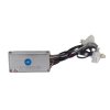
57350

The display looks like this...

57351

Am I right in thinking there should be something like 5v running up to the display all the time the battery is connected? I have taken the controller cover off but unfortunately the contents are potted. I have done a considerable bit of searching but couldn't find any wiring diagrams or schematics.

Any help would be very much appreciated.

Regards,

Les
 

saneagle

Esteemed Pedelecer
Oct 10, 2010
6,785
3,132
Telford
Hi,

Whilst I am an eBike noob I am reasonably competent at electronics but could do with some help with this.

I just bought this bike 2nd hand, advertised for spares or repair as the battery wasn't charging, the seller stated the charger flashes red momentarily and then nothing. However upon getting it home the battery (26cv9ah) was reading 28v and when I connected the charger the red light came on as expected. (It just occurred to me that it might behave differently if charged on the bike?)

Anyway the long and short if it is that nothing happens when pressing the on/off button on the display. I am thinking it can only be the controller, wiring or display The controller has 28v at the connector from the battery. It looks like this one...
View attachment 57350

The display looks like this...

View attachment 57351

Am I right in thinking there should be something like 5v running up to the display all the time the battery is connected? I have taken the controller cover off but unfortunately the contents are potted. I have done a considerable bit of searching but couldn't find any wiring diagrams or schematics.

Any help would be very much appreciated.

Regards,

Les
The display runs on battery voltage, not 5v. It takes it's supply directly from a branch off the main battery wires inside the controller, so it works independently.

When your battery switches off after switching on, there are two main reasons:
1. It's knackered
2. You have a blown MOSFET in the controller, which can either be a dead short, which you can test that by checking the continuity between the two battery wires into the controller, or it causes the over-current control to trip because the motor can't turn. You test that by doing a MOSFET test. Search the forum for how to do that. It's very easy if you have a meter.
 

PointyUK

Pedelecer
Apr 21, 2024
31
2
The display runs on battery voltage, not 5v. It takes it's supply directly from a branch off the main battery wires inside the controller, so it works independently.

When your battery switches off after switching on, there are two main reasons:
1. It's knackered
2. You have a blown MOSFET in the controller, which can either be a dead short, which you can test that by checking the continuity between the two battery wires into the controller, or it causes the over-current control to trip because the motor can't turn. You test that by doing a MOSFET test. Search the forum for how to do that. It's very easy if you have a meter.

Thanks for the reply.

I haven't tried putting a load on the battery yet, only measured it's voltage.

There is no continuity between the battery input terminals on the controller. I will check voltage at the display tonight when I get home from work and also take some photos. Also all connectors look in really good condition with no sign of corrosion.

I think I have identified what each connector belongs to with the exception of 2 that were not connected. There is a double connector 2 pin black connector, which I think might be brake sensors (there are none fitted on this model) . There is also another 3 pin connector with grey, yellow and red wires that have no idea what it is for.

There is a hole in the display button cover where the on/off button is but the PCB doesn't look corroded and the button feels like it is clicking. I get absolutely nothing on the display, not even a flicker of life. Wouldn't a motor problem only affect things one the PAS kicks in or even show up as a malfunction on the display?

I have a 30v 10a bench supply that I could use for testing, would the display fire up if it is the only thing connected to the controller and powered by the bench supply?

Regards,

Les
 

saneagle

Esteemed Pedelecer
Oct 10, 2010
6,785
3,132
Telford
Thanks for the reply.

I haven't tried putting a load on the battery yet, only measured it's voltage.

There is no continuity between the battery input terminals on the controller. I will check voltage at the display tonight when I get home from work and also take some photos. Also all connectors look in really good condition with no sign of corrosion.

I think I have identified what each connector belongs to with the exception of 2 that were not connected. There is a double connector 2 pin black connector, which I think might be brake sensors (there are none fitted on this model) . There is also another 3 pin connector with grey, yellow and red wires that have no idea what it is for.

There is a hole in the display button cover where the on/off button is but the PCB doesn't look corroded and the button feels like it is clicking. I get absolutely nothing on the display, not even a flicker of life. Wouldn't a motor problem only affect things one the PAS kicks in or even show up as a malfunction on the display?

I have a 30v 10a bench supply that I could use for testing, would the display fire up if it is the only thing connected to the controller and powered by the bench supply?

Regards,

Les
The battery wires go directly to each motor phase wire but they're blocked by the MOSFETs. When the controller is switched on and working, it controls the MOSFETS by opening them in timed commutation pulses. If a MOSFET is blown, it would be permanently open, so huge current would be allowed through a motor phase. If both a high and low MOSFET blow, you get a dead short to ground.

If your battery is nackered, there's normally enough power to charge up the main capacitor in the controller, so when you switch on, there's enough power in the capacitor to light the LCD and power the sensors for a second or two before it runs at and the LCD fades and goes off.
 

PointyUK

Pedelecer
Apr 21, 2024
31
2
Here is photo of my controller...

57381

and here is the display board...

57382


When measuring the voltage on the display across vcc & gnd I get -22v (negative) which seems odd.
 

saneagle

Esteemed Pedelecer
Oct 10, 2010
6,785
3,132
Telford
Back of display pcb...

View attachment 57383
OK, there's the 5v regulator and microprocessor. It must use one of those piddly transistors on the first side to switch on the power, which is a bit unusual.

You should have battery voltage on VCC. When you switch on, it latches it to a wire that goes back to power the controller - probably O/F (on/off?). If it's analogue, speed should be 1v, 2v and 3v for the different levels. That leaves DIG for the lights - possibly high and low 5v as a signal to the controller CPU to switch on the lights. If its digital, you normally see tx and rx for the data wires.

You need to start by checking the battery voltage on the controller side display connector with it disconnected from the display, but connected to the battery.
 

PointyUK

Pedelecer
Apr 21, 2024
31
2
Thanks for helping.

I had already done that and the result is the weird -22v between the orange (vcc) and black (gnd) wires on the display connector at the controller. I am pretty sure all the polarities are correct. When plugged in, at the display end I got nothing until I de-soldered the power wires and then I get -22v again.
 

PointyUK

Pedelecer
Apr 21, 2024
31
2
Also, not really relevant but the display doesn't have a lights button it is instead used for diagnostics according to the manual.
 

saneagle

Esteemed Pedelecer
Oct 10, 2010
6,785
3,132
Telford
Also, not really relevant but the display doesn't have a lights button it is instead used for diagnostics according to the manual.
Did you check the voltage on the wires going into the controller? The display power wires are normally simple branches off them.
 

PointyUK

Pedelecer
Apr 21, 2024
31
2
Did you check the voltage on the wires going into the controller? The display power wires are normally simple branches off them.
It's hard to tell what's going on because of the horrible silicone potting, which I am not convinced has done it's job. I am slowing picking away at it, trying to to destroy the PCB. :rolleyes:

Last night at 5pm I hooked up a set of LEDs to the battery, they are not drawing a massive current but they are still on this morning, so at least the battery is holding some charge. EDIT: There is 26.5v on the battery this morning. Does the BMS shut off the output if the voltage gets to low? Obviously I don't want to take the voltage too low and destroy the cells.

I also re-soldered the display connection wires and hooked it up to the bench supply. All the LEDs light up and then just the mode light comes on. Pressing the mode button changes the mode LED as expected. On/off and Giant (Light) buttons seem to do nothing. No voltage is detected on the speed pin.
 
Last edited:

PointyUK

Pedelecer
Apr 21, 2024
31
2
Obviously the goal here is to see if it is cost effective to repair this bike. As the battery seems ok, I guess the absolute worst case is a new motor, controller and display. :oops:
 

saneagle

Esteemed Pedelecer
Oct 10, 2010
6,785
3,132
Telford
Obviously the goal here is to see if it is cost effective to repair this bike. As the battery seems ok, I guess the absolute worst case is a new motor, controller and display. :oops:
The battery probably isn't OK. You need to put it under a load to see if it shuts down. Hot off the charger, it should be the same voltage as the charger, which is normally 29.4v. The controller will shut down at about 21v and the battery will shut itself down at about 19v.

If it were my bike, I'd keep the motor and get a new 36v battery and controller for it for about £200. You'd also need a pedal sensor, though the existing torque sensor might be able to work in parallel with the throttle if it has 5v analogue output.
 

PointyUK

Pedelecer
Apr 21, 2024
31
2
The battery charged up to 28.7v but I haven't checked to see what the charger is outputting.

As I don't even know if the motor is good yet, I will keep playing with what I have for now.
 

PointyUK

Pedelecer
Apr 21, 2024
31
2
I have managed to clean up the worst of the silicone from the component side of the controller...

57405

The supply to the display is not a simple branch it looks like it is controlled by Q10, but where it comes from I have not worked out yet. (there appears to be a large unsoldered pin, just above the negative battery wire)

It looks like the display power button simply sends the supply voltage to the 0/f pin of JP1 via R20.(Actually marked on/off on the controller PCB)

The MCU of the display is a Holtek HT46F47E. As all the LEDs come on/go off when powered and the mode light is changing, I am assuming that it is functional.
 

saneagle

Esteemed Pedelecer
Oct 10, 2010
6,785
3,132
Telford
I have managed to clean up the worst of the silicone from the component side of the controller...

View attachment 57405

The supply to the display is not a simple branch it looks like it is controlled by Q10, but where it comes from I have not worked out yet. (there appears to be a large unsoldered pin, just above the negative battery wire)

It looks like the display power button simply sends the supply voltage to the 0/f pin of JP1 via R20.(Actually marked on/off on the controller PCB)

The MCU of the display is a Holtek HT46F47E. As all the LEDs come on/go off when powered and the mode light is changing, I am assuming that it is functional.
Did you check the continuity between the red battery wire pad and the one for the orange display wire. It wouldn't make sense for it to be switched by a transistor because there's no way to switch the transistor on until the display is switched on.

First step should be to switch everything on and follow the battery voltage.
 

PointyUK

Pedelecer
Apr 21, 2024
31
2
Did you check the continuity between the red battery wire pad and the one for the orange display wire. It wouldn't make sense for it to be switched by a transistor because there's no way to switch the transistor on until the display is switched on.

First step should be to switch everything on and follow the battery voltage.

Yes that was the first thing I checked, there is no connection between battery + and the orange/ display vcc. The transistor could be controlled by the MCU on the controller, maybe it does startup checks before switching it?

It's hard to trace because I can't see the back. I guess I need to see if heating up the case will release the PCB and whatever gunk is behind it.
 

saneagle

Esteemed Pedelecer
Oct 10, 2010
6,785
3,132
Telford
Yes that was the first thing I checked, there is no connection between battery + and the orange/ display vcc. The transistor could be controlled by the MCU on the controller, maybe it does startup checks before switching it?

It's hard to trace because I can't see the back. I guess I need to see if heating up the case will release the PCB and whatever gunk is behind it.
Did you follow the battery voltage to see where it stops?
 

PointyUK

Pedelecer
Apr 21, 2024
31
2
Did you follow the battery voltage to see where it stops?
No, not yet but I did finally get the whole PCB out of the case...

57410

There are some possible signs of water ingress.


I am still puzzled about the display though.

Why does the display go though it's start up routine when power is applied? Surely it should wait until it is turned on.

Why does it not show the battery level?

What is DIO? Digital out, digital I/O? Although it says the MCU pins are bi-directional I think they are either configured in software as input or output.

I am nearly done with making a schematic for the display which might shed some light on things.

Also, before I decide how to proceed any idea if I can test the torque sensor? As these are also expensive, I need to know if it works.

Finally you said about replacing the battery/controller with 36v versions. Wouldn't that fry the motor if is designed for 26v?