E Voyager Electric Mountain Bike Drag

Budgie1

Finding my (electric) wheels
Jul 21, 2014
11
0
55
Hi. I've recently bought my first e-bike through gumtree, an E Voyager Pro Rider. It was nearly new and whilst I know its a budget bike I have been very impressed with it especially as it was not expensive. I've discovered one issue this weekend which I would appreciate any advice.

This weekend I noticed on a run that when I hit a piece of flat of slightly downhill road, I would stop pedalling and expect the bike to freewheel. What happened was a few seconds after the motor cut out I felt what seemed to be considerable drag on the bike slowing it down. This didn't feel normal compared to my previous experiences and overall the bike felt harder to ride.

I wonder does this bike have some sort of battery regeneration which is causing this, reason I mention this is that I've noticed on runs where I do a fair bit of pedalling the battery indicator seems to increase to a higher level. The rear brake is also some sort of drum type so I wonder could this be a cause if it was binding.

I'm based in Northern Ireland, I wonder are there any good bike shops familiar with e-bikes over here so I could get it looked at.
 
D

Deleted member 4366

Guest
With everything switched off, lift the front wheel off the ground and spin it. It should spin freely. Then do the same with the back wheel. Spin it in the forward direction. It should also spin freely. If it doesn't, you have to find out whether the brake or motor is stopping it. It's most likely the brake that's not properly adjusted.

To find out which it is turn the wheel by hand in each direction. When you turn it backwards slowly, you should be able to feel and hear the motor turning. If you can feel the motor turning when you turn the wheel forwards, your clutch is jammed. If the wheel is just stiff to turn forwards with no motor noise and feel, your brake needs adjusting.

Report back which of the two it is if you need help to fix it.
 

Budgie1

Finding my (electric) wheels
Jul 21, 2014
11
0
55
Thanks d8veh, appreciated the quick reply. I didn't notice any stiffness turning wheel forward and to be honesty couldn't really feel/hear the motor turning either direction. I'm only getting used to the bike so will perform a few more tests on the road. I know part of the experience is the sensation the motor comes off power when stopping pedalling that could feel like drag. It seems hit or miss, sometimes it seems to freewheel down hills really fast and then sometimes it feels like something is binding and causing the bike to slow. I also realise that sometimes a road that looks like a slight decline and able to freewheel might not in fact be downhill so this needs to be tested as well.

Last night on way home from work I noticed on a steel hill the motor really was not up to the gradient at all and stalled easily. It needed a fair bit of pedal assist but I was able to remain seated. Probably due to the budget nature of the bike. The last 3 miles on the flat the bike has no problem getting up to cruising speed.

Yesterday also a celebration day - in 22 years of working life I've never cycled to work until yesterday. The e-bike is a revelation allowing a sweat free arrival. Today I also took the bike. Reasonably fit but the electric assistance just makes the experience more enjoyable, appeals to my geeky side, makes me feel safer in traffic, extends my range and from a fitness perspective my view is everything in moderation so it allows reasonable exercise with greater output. I'm sure this will remain a lifelong hobby and I'm already looking for a lighter ebike with great torque for steep hills, great range and a personal preference of a throttle control as well as pedal assist. I've no real issue with the 15mph speed restriction (although 20mph would be nicer) and am happy enough working the pedals to go faster.
 
D

Deleted member 4366

Guest
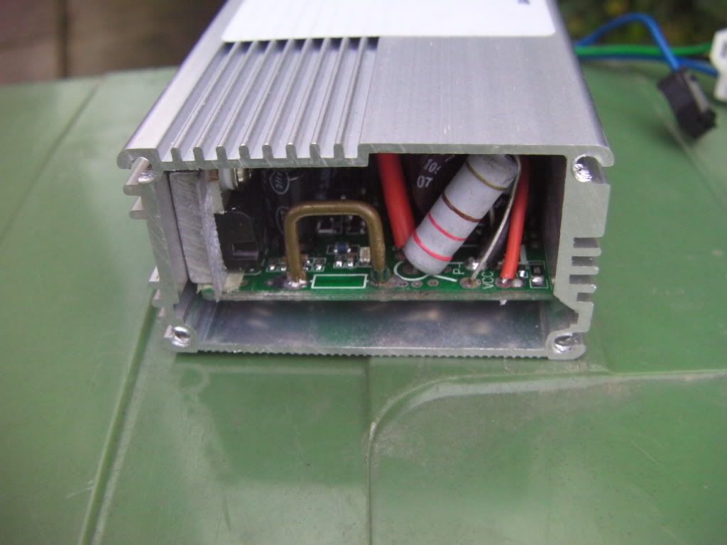
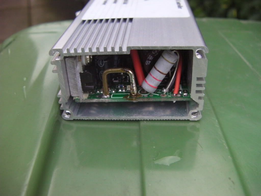
You can get a bit more hill-climbing torque by adding some solder to the shunt in the controller, which increases the current it allows. You can get up to 30% more torque.

Before:


After:


Budgie1

Finding my (electric) wheels
Jul 21, 2014
11
0
55
Wow, I will try this tonight thanks. I notice only the right leg has additional solder added is this the method to follow or should additional solder be added to the complete U shunt.
 
D

Deleted member 4366

Guest
You should solder about 25% of the length of it. It doesn't really matter where you start and finish. Try and get some thickness to it. Don't be greedy and go too far otherwise your BMS might start cutting out. If you do go too far, you can wipe some back off with the soldering iron.

On some controllers (LSDZS), the shunt lies along the PCB under the big capacitor. If you're really unlucky, you'll have a solid state shunt of fixed value in which case you have to do a bit of maths and then find a similar one of the correct value to solder over the top.

If you want to be really clever, you can be precise in your increase. Yo set your voltmeter to mV, then connect it to one of the wires between the battery and the controller. You need a distance of about 6" or more. The probes connect to the same wire but in different places, e.g. at the controller connector and at the terminal at the top of the compartment under the battery base-plate.

Give your bike full throttle and then apply the brake to slow the wheel right down running at full power. Don't stop the motor. You'll see the mV peak before it gets that slow. Note the reading on the voltmeter. After you've added some solder, do the same test again and note the new reading in mV. the difference is proportional to the increase in current, so if it goes from 10mV to 12mV, that's a 20% increase from 15A to 18A. 18A should be the target.
 

Budgie1

Finding my (electric) wheels
Jul 21, 2014
11
0
55
I took apart my controller to attempt the solder shunt. I've attached a few photos of the controller I don't see anything resembling the shunt so perhaps it is solid state. Is it possible to replace with another controller so I can increase the current and get a bit more hill climbing torque. It would also be interesting to be able to increase the top speed by a few mph to the upper end of tolerances.
 

Attachments

D

Deleted member 4366

Guest
It'll be under all those wires, normally somewhere near where the red battery wire is soldered.
 

derf

Esteemed Pedelecer
Aug 4, 2014
1,007
766
54
I took apart my controller to attempt the solder shunt. I've attached a few photos of the controller I don't see anything resembling the shunt so perhaps it is solid state. Is it possible to replace with another controller so I can increase the current and get a bit more hill climbing torque. It would also be interesting to be able to increase the top speed by a few mph to the upper end of tolerances.
could any of you define what a shunt is and does (and how the soldering helps)? many thanks
 
D

Deleted member 4366

Guest
The shunt is a component that has a stable very low resistance. The current from the battery goes directly through it, but because it has a little bit of resistance, the voltage is a bit higher in one side than the other. The more current that flows, the greater the voltage difference.

As an example with a 36v battery and a controller giving it's maximum 15 amps, there will be 36v on the battery side of the shunt and maybe 35.985v on the controller side (0.015v difference).

The controller's CPU keeps an eye on that voltage difference, and when it reaches 0.015v, it cut's back the power so that you can't go any higher.

If you add solder to the shunt, it reduces the resistance, so there's less voltage drop. If you can reduce it to 0.010v at 15 amps, then the controller will continue to allow power right up until it sees 0.015v which will happen at about 22 amps. Therefore you have increased the maximum current taken from the battery from 15 amps to 22 amps.

Of course if your battery is knackered or limited to 20 amps, it'll start cutting off, so you have to make sure it's capable of giving the current that the modified controller demands. Most batteries can manage 20 amps. An increase from 15 to 18 amps makes a significant difference without straining the battery too much.

How do you know how far to go? As a rough rule of thumb, about 25% of the length of the shunt will take you from 15A to 18A. It's best to use a wattmeter to measure the current before and after if you want to be sure.

There's two types of shunts commonly used in controllers: Solid state ones which are black flat square things


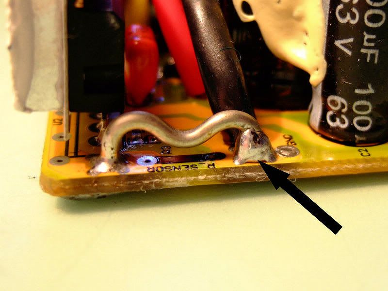
and wire types that look like a bridge of wire


That arrow points to a small blob of solder added. I'd go about twice as far.

If you're lucky, the shunt is nicely positioned behind the end-plate, like this one that I did:


otherwise it could lie anywhere on the pcb, although normally near the red battery wire.

Some high power controllers have several shunts in parallel.

Your battery BMS also has a shunt. You can get it to allow more current too by soldering it.

You can also reduce the current allowed by the controller by filing or crimping notches in the shunt to increase its resistance.

Lastly, if you have the solid state type, you can reduce their resistance by soldering another one on top of it. They're sometimes already piggy-backed two or three deep. You have to calculate the value of the additional one using this formula:

Where Rtot is the new resistance, R1 was the old one, and R2 is the new additional one.
 

derf

Esteemed Pedelecer
Aug 4, 2014
1,007
766
54
The shunt is a component that has a stable very low resistance. The current from the battery goes directly through it, but because it has a little bit of resistance, the voltage is a bit higher in one side than the other. The more current that flows, the greater the voltage difference.

As an example with a 36v battery and a controller giving it's maximum 15 amps, there will be 36v on the battery side of the shunt and maybe 35.985v on the controller side (0.015v difference).

The controller's CPU keeps an eye on that voltage difference, and when it reaches 0.015v, it cut's back the power so that you can't go any higher.

If you add solder to the shunt, it reduces the resistance, so there's less voltage drop. If you can reduce it to 0.010v at 15 amps, then the controller will continue to allow power right up until it sees 0.015v which will happen at about 22 amps. Therefore you have increased the maximum current taken from the battery from 15 amps to 22 amps.

Of course if your battery is knackered or limited to 20 amps, it'll start cutting off, so you have to make sure it's capable of giving the current that the modified controller demands. Most batteries can manage 20 amps. An increase from 15 to 18 amps makes a significant difference without straining the battery too much.

How do you know how far to go? As a rough rule of thumb, about 25% of the length of the shunt will take you from 15A to 18A. It's best to use a wattmeter to measure the current before and after if you want to be sure.

There's two types of shunts commonly used in controllers: Solid state ones which are black flat square things


and wire types that look like a bridge of wire


That arrow points to a small blob of solder added. I'd go about twice as far.

If you're lucky, the shunt is nicely positioned behind the end-plate, like this one that I did:


otherwise it could lie anywhere on the pcb, although normally near the red battery wire.

Some high power controllers have several shunts in parallel.

Your battery BMS also has a shunt. You can get it to allow more current too by soldering it.

You can also reduce the current allowed by the controller by filing or crimping notches in the shunt to increase its resistance.

Lastly, if you have the solid state type, you can reduce their resistance by soldering another one on top of it. They're sometimes already piggy-backed two or three deep. You have to calculate the value of the additional one using this formula:

Where Rtot is the new resistance, R1 was the old one, and R2 is the new additional one.
many thanks for the helpful reply (it clarifies lots), since batteries have shunts too I guess it couldn't do any harm?
 

trex

Esteemed Pedelecer
May 15, 2011
7,703
2,671
The limit on the battery is much more critical. Leave it alone.
you'll kill your battery if you modify the battery shunt.