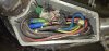
The motor is three-phase, so there are three thick phase wires that provide power to it. The controller needs to know the position of the motor so that it can fire the energy pulses down each phase at the right time. It uses three hall sensors for that. The hall sensors are powered by 5v (thin red and black wires). They send their signals back to the controller by the thin blue, yellow and green wires. If the controller doesn't get the correct timing signal, you get the grinding noise.
If the controller continues to fire incorrectly timed pulses, the current is huge and it can cause the MOSFETs to blow. The MOSFETs are like electronic switches/gates that let the pulses of energy through to the motor.
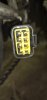
First find the hall sensor connector inside the controller compartment. It's a large white block with the 5 wires in it. Check that it's clean and put a blob of silicone grease in it to protect it from water. Don't put anything back in the compartment because you have to do some tests to see what's wrong.
Here's how to test an ebike system. Start with tests 2, 5 and 6. tests 2 and 5 with the controller switched on and powered. Test 5 with the phase and battery wires disconnected:
1. Measure the voltage at controller's battery connector. Obviously should be battery voltage. 36v - 42v for a 36v battery would be an acceptable range, but if you've fully charged the battery and it's less than 41v, it needs some sorting.
2. Measure the voltage on the 5v rail. You can measure that between any ground (black) and any of the reds going to throttle, PAS or motor halls. It should be around 5v.
3. Check throttle signal wire voltage on it's connector while connected. it's the wire that's not red or black on the throttle connector. Should give about 1v to 4v when you twist the throttle. If there's more than one wire, your meter will find it. It's the one that's between 1v and 4v, assuming that it works.
4. Check that the pedal assist sensor is pulsing. Measure the PAS signal wire while turning the pedals slowly. Should pulse 5v on and off every time a magnet passes the sensor. The signal wire is the one that's not red or black.
5. Check the motor hall signal wires (blue green and yellow) on the motor connector at the controller. They should each pulse with 5v going on and off as you rotate the wheel
BACKWARDS.
6. Mosfet test. Disconnect the motor cable and battery from the controller. Measure the resistance (200k scale) between the red battery connection and each of the three phase wire connections, then repeat with the black battery wire. Each set of 3 readings should be the same as each other and in the range 7K -24K. Though can be higher as long as they're all the same. Due to the capacitor across the battery wire, you can get a constantantly changing measurement while it charges. In that case, try swapping your probes round. Even though can be a moving result, the only important thing is that all three move in a similar way.
Wiring diagram in this thread. Yours is slightly different in that you have the little potentiometer to adjust the speed instead of bridging the white wires:
Hello, I'm after a little help replacing my Cyclamatic power plus controller. Where do I start?? The old controller when opened had an exploded capacitor, I replaced the capacitor but it was dead, obviously what ever made the capacitor explode in the first place had affected other parts of the...

www.pedelecs.co.uk